
| Type Model | Announced | Available | Marketing Withdrawn | Service Discontinued | Replaced By |
|---|---|---|---|---|---|
| 7011-250 | 1993/09/21 | 1993/10/15 | 1997/07/18 | - | 7043-140 |
The RS/6000* family of workstations and servers offers a broad range of powerful, scalable computing solutions. Operating system support is provided by AIX*, best rated UNIX** operating system by noted industry consultant D. H. Brown. Many thousands of applications are available spanning commercial and technical needs.
(For IBM US, No Longer Available as of July 18, 1997)
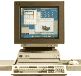
The IBM* RS/6000 Model 250 is flexible and powerful, and performs well as either a graphics workstation or a server. Driven by a 66MHz PowerPC 601* microprocessor, it offers growth capability from 16MB up to 256MB of error checking and correction (ECC) memory, optional internal fixed disk up to 2GB, up to a maximum of seven SCSI devices on the SCSI bus, an optional 2.88MB diskette drive, an optional graphics adapter, and two 32-bit Micro Channel* card slots.
 | Combines easy customer configuration and installation with solid performance. |
| Offers compute and graphics performance for cost-effective, entry-level workstation and server solutions. |
| Provides high-performing graphics adapters which connect directly to the PowerPC 601 local processor bus to provide accelerated 2D performance. With the AIXwindows* 3D feature, Softgraphics support is provided for full-function 3D graphics capability. |
| Maintains binary compatibility with other RS/6000 family members and support for both AIX Version 4 and AIX Version 3.2.5. |
| AIX, IBM's operating system, conforms to major, open systems standards with thousands of applications available. |
| 16MB to 256MB of memory, using standard PS/2* memory SIMMs with Error Checking and Correction (ECC) for high reliability and availability. |
| Open system design: industry-standard memory, industry standard integrated SCSI-2 and Ethernet** (10 Base 5, 10 BaseT) controllers and two industry-standard Micro Channel slots, for additional growth capability. |
| LAN-dependent, LAN-attached or stand-alone workstation. |
| Easily-configured models provide flexibility. |
IBM's innovative PowerPC* technology delivers breakthrough value and performance to the 250 Series workstations and servers. The floating-point performance of these systems makes them a natural for entry, technical engineering/scientific applications, while their integer performance and powerful transaction processing capabilities provide a good environment for running business applications. These cost-effective, entry-level systems are ideal in multiuser environments and are binary compatible with other members of the RS/6000 family and support both AIX Version 4 and AIX Version 3.2.5. The Model 250 is versatile, providing paging over LANs and remote IPL, and can be easily enhanced with optional features and supported devices.
Base Model Configuration 250
The entry POWERstation/POWERserver 250 can function without a fixed disk in a LAN environment or, with a fixed disk and diskette drive added, in a stand-alone environment. Customers can upgrade memory and add features to enhance the system.
The standard features of the POWERstation/POWERserver 250 are:
| 66MHz PowerPC 601* processor |
| Eight slots for SIMM memory cards |
| 16MB memory (Four 4MB SIMM memory cards that use the first four of eight available slots) |
| One integrated SCSI-2 controller |
| One integrated Ethernet controller |
| Standard Device Ports/Connectors: |
 | Keyboard/Speaker Port |
| Mouse Port |
| Tablet Port |
| Two Serial Ports |
| Parallel Printer Port |
| SCSI-2 Port |
| Ethernet Port |
This requires only four memory slots, up to 128MB may be added in the other four slots for a maximum of 256MB.
Note: Standard with the POWERstation/POWERserver 250 series is the ability to attach the Ethernet controller to either Thick or Twisted Pair Ethernet media. For connection to Thick (10 Base 5) Ethernet media, the output connector is a Thick 15-pin D-shell "slide-latch" type that is compatible with IEEE 802.3 Section 7.6. For connection to Twisted Pair (10 Base T) Ethernet media, use the additional converter that is shipped standard with the POWERserver 250 series. For connection to Thin (10 Base 2) Ethernet media, use an optional external Transceiver (Feature Code #4223).
The base configuration model of the POWERstation/POWERserver 250 series.
Business Solutions
The POWERstation/POWERserver 250 series supports customers' business objectives by providing a high-performance, desktop workstation/server solution for compute-intensive technical applications or multi-user commercial server applications. With either the 2D GXT100 graphics adapter or GXT150 graphics adapter the POWERstation/POWERserver 250 series workstation models are ideally suited to 2D environments where high-performance and low cost-per-seat are important. With the AIXwindows 3D feature, Softgraphics support is provided to enable full-function 3D graphics capability on all supported graphics adapters, including the GXT100 and GXT150 graphics adapters. This feature provides cost-effective and scalable graphics performance and consistent functions for the entry 3D environments. When configured with either a POWER Gt4e or GTO Accelerator graphics adapter and appropriate software, more demanding 3D applications are enabled. POWERstation 25S, with its standard 1 GB disk drive and 8-port adapter, is a cost-effective entry server for retail, branch banking, wholesale and plant floor applications. Memory capacity of up to 256 MB and internal fixed disk capacity of up to 2 GB, coupled with a variety of input/output devices, graphics, and communications features, are available to configure the system as a powerful, entry POWERstation or POWERserver for a wide range of business solutions.
The POWERstation/POWERserver 250 series desktop workstations utilize IBM's PowerPC Architecture* and are binary compatible with the IBM RS/6000 POWERstation/POWERserver family of systems, with application portability and high throughput levels. All AIX/6000 applications written for POWER-based RS/6000s (models available before 9/21/93) will run on the PowerPC 601-based* RS/6000s without recompilation. (The only exception to this statement would be applications written using kernel extensions which use certain privileged Assembler instructions. IBM is not aware of any applications using these instructions.) The POWERstation/POWERserver 250 series with AIX/6000 Version 3.2.5, conforms to many industry-standards in the open system environment -- a key factor to enable customers to develop and port applications.
Investment Protection
The POWERstation/POWERserver 250 series, with AIX/6000 3.2.5, offers interoperability with other IBM and other vendor host systems, expanding the usefulness of those systems and maximizing the utility of the 250 series. Any POWERstation/POWERserver 220 or 230 series machine can be upgraded to a 25E. The POWERstation/POWERserver 250 series, with its PowerPC 601* processor offers competitive fixed-point processing and floating-point processing for the entry workstation market. The POWERstation/POWERserver 250 series can be configured as a diskless or dataless system with integrated SCSI-2 and Ethernet controllers. Because of its optional feature offerings it can also be configured as an independent workstation, a file or communications server, or a distributed system.
User Productivity
The POWERstation/POWERserver 250 series supports AIXwindows* Environment/6000, which is based on the MIT (Massachusetts Institute of Technology) X window System, and includes a graphical user interface based on OSF/Motif**. Through the use of industry-standard OSF/Motif, savings may be realized in end-user training and application development. Additionally, savings in hardware may be realized through the use of LAN-attached Xstations, to reduce cost per seat.
AIXwindows Environment/6000, based on the versatile OSF/Motif graphics user interface, provides the user with icons to represent files, printers and system objects, and allows the user to manipulate the file system through the icons. Support for InfoExplorer*, the online documentation aid, offers the user flexible access to online documentation using task index, hypertext jump points, and search features. These features allow users to become participant quickly, minimizing training and reducing costs.
Growth Enablement
The POWERstation/POWERserver 250 series is designed to grow with the customer's requirements. Memory can be increased to a maximum of 256MB. A maximum of seven SCSI devices (including optional internal fixed disk drive) can be attached.
The integrated SCSI-2 controller attaches up to seven SCSI-1 devices or four SCSI-2 devices. One internal disk drive may be installed in the POWERstation/POWERserver 250 series. A 200MB, 540MB, 1GB, or 2GB drive can be installed. Additional external devices may be attached, or by using Differential High-Performance External I/O Controllers (#2420) and external DASD Expansion Units, up to 30 GB of total disk storage may be configured. The integrated Ethernet controller and the PowerPC 601* local processor bus slot for graphics adapters allow the user to have a LAN attachment and additional I/O devices and graphics without utilizing any of the Micro Channel* slots.
Two Micro Channel feature card slots (form factor 3) are available for additional features such as a token-ring adapter, communications processors and high-performance 3D graphics processors.
System Management
A system installation and management facility is provided as part of the operating system. The System Management Interface Tool (SMIT) facilitates the performance of system management tasks, such as software installation and configuration, device configuration and management, problem determination, and storage management. Support is also provided for the use of an ASCII terminal as the system console as well as remote installation of the system on a LAN.
AIX/6000 is designed to meet the NCSC (National Computer Security Center) trusted computer system evaluation criteria class C2 security support requirements.
                                                         Std Device
        CPU In                  Internal        Micro     Ports &
Model    MHz       Memory       Fixed disk     Channel   Connection
------  -----   -------------   -----------    -------   ----------
 250    66      16MB to 256MB   0 to 2GB       2 Slots      Yes

        Ethernet     Diskette   Graphics                  SCSI
Model   Controller   Drive      Adapter     Display    Controller
------  ----------   --------   --------    --------   ----------
 250       Yes       Optional   Optional    Optional     SCSI-2
External Storage Machines
| IBM Magstar MP Tape Subsystem |
| IBM Magstar MP 3570 Model C00 Tape Subsystem |
| IBM Magstar MP 3570 Model C01 Tape Subsystem |
| IBM Magstar MP 3570 Model C02 Tape Subsystem |
| IBM Magstar MP 3570 Model C11 Tape Subsystem |
| IBM Magstar MP 3570 Model C12 Tape Subsystem |
| IBM Magstar MP 3575 Tape Library Dataserver Model L06 |
| IBM Magstar MP 3575 Tape Library Dataserver Model L12 |
| IBM Magstar MP 3575 Tape Library Dataserver Model L18 |
| IBM Magstar MP 3575 Tape Library Dataserver Model L24 |
| IBM Magstar MP 3575 Tape Library Dataserver Model L32 |
| 3590-B1A -- Magstar 3590 Tape Subsystem |
| 3590-B11 -- Magstar 3590 Tape Subsystem |
| IBM 3590-C12 Magstar Silo Compatible Frame |
| IBM 3995 Model C60 Optical Library |
| IBM 3995 Model C62 Optical Library |
| IBM 3995 Model C64 Optical Library |
| IBM 3995 Model C66 Optical Library |
| IBM 3995 Model C68 Optical Library |
| IBM 7131 Model 105 SCSI Multi-Storage Tower |
| IBM 7203 Model 001 Portable Disk Unit |
| IBM 7204 Model 001 1GB External Disk Drive |
| IBM 7204 Model 010 1GB External Disk Drive |
| IBM 7204 Model 112 1.1GB External Disk Drive |
| IBM 7204 Model 113 2.2 GB External Disk Drive |
| IBM 7204 Model 114 4.5 GB External Disk Drive |
| IBM 7204 18.2 GB External Disk Drive Model 118 |
| IBM 7204 Model 139 9.1GB External Disk Drive |
| IBM 7204 Model 315 External Disk Drive |
| IBM 7204 Model 317 2.2GB External Disk Drive |
| IBM 7204 Model 320 External Disk Drive |
| IBM 7204 Model 325 4.5GB External Disk Drive |
| IBM 7204-339 RS/6000 External Disk Drive |
| IBM 7204-402 External Disk Drive |
| IBM 7204-404 External Disk Drive |
| IBM 7204 18.2 GB External Disk Drive Model 418 |
| IBM 7205-311 35GB External Digital Linear Tape Drive |
| IBM 7206 Model 001 2.0GB External 4mm Tape Drive |
| IBM 7206 Model 005 4.0GB External 4mm Tape Drive |
| IBM 7206 Model 110 12 GB External 4mm DDS-3 Tape Drive |
| IBM 7207 Model 001 150MB 1/4-inch Tape Drive |
| IBM 7207 Model 011 525MB External 1/4-Inch Cartridge Tape Drive |
| IBM 7207 Model 012 1.2GB External 1/4-Inch Cartridge Tape Drive |
| IBM 7207 Model 315 13GB 1/4-Inch Tape Drive |
| IBM 7208 Model 001 2.3 GB 8mm Tape Drive |
| IBM 7208 Model 011 5.0 GB 8mm Tape Drive |
| IBM 7208 Model 341 20GB External 8mm Tape Drive |
| IBM 7209 Model 001 650MB R/W Optical Disk Drive |
| IBM 7209 Model 002 1.19GB R/W Optical Disk Drive |
| IBM 7209 Model 003 2.6GB Optical Disk Drive |
| IBM 7210 Model 001 External CD-ROM Drive |
| IBM 7210 Model 005 External CD-ROM Drive |
| IBM 7210 Model 015 8X CD-ROM Drive |
| IBM 7331 Model 205 8mm Tape Library |
| IBM 7331 Model 305 8mm Tape Library |
| IBM 7332 Model 110 4mm DDS-3 Tape Cartridge Autoloader |
| IBM 7336 Model 205 4mm Tape Library |
| IBM 9334 Model 500 Deskside Expansion Unit (Requires dedicated SCSI I/O Controller) |
| IBM 9334 Model 501 Deskside Expansion Unit (Requires dedicated SCSI I/O Controller) |
| IBM 9348-012 Magnetic Tape Unit |
| IBM 3514 Model 212 Disk Array Subsystem (Note 1) |
| IBM 3514 Model 213 Disk Array Subsystem (Note 1) |
| IBM 7135 Model 010 RAIDiant Array (Note 1) |
| IBM 7135 Model 110 RAIDiant Array (Note 1) |
External Storage Notes:
| IBM 3490 Enhanced Capability Magnetic Tape Subsystem, model E01 |
3D Input Device
| IBM 6094 Spaceball Model 30 |
X Stations
| IBM 7010 Model 120 |
| IBM 7010 Model 130 |
| IBM 7010 Model 140 |
| IBM 7010 Model 150 |
ASCII Terminals
| IBM 3151 Model 310/410 (1) |
| IBM 3153 Model BA3/BG3/BW3 |
| IBM 3161 (1) |
| IBM 3162 (1) |
| IBM 3163 (1) |
| IBM 3164 (1) |
| DEC VT100 |
| DEC VT220 |
| DEC VT320 |
| DEC VT330 |
| WYSE 30 |
| WYSE 50 |
| WYSE 60 |
| WYSE 350 |
(1) National language support is provided through the use of Cartridge 8859/1.2 inserted in the terminal and appropriate keyboard.
IBM Displays
| POWERdisplay 16S (#3603) |
| POWERdisplay 16 (#3600) |
| POWERdisplay 17 (#3607) |
| POWERdisplay 19 (#3601) |
| IBM 1091-051 16-inch Color Display (1024 x 1280 72Hz NI) |
| IBM 5081 16-inch Color Display (1024 x 1280 60Hz only) (b) |
| Feature code #1280 required |
The IBM 6091 16-inch monitor has an actual viewable screen size of 14.8 inches when measured diagonally.
75 Hz NI)
The IBM 6091 19-inch monitor has an actual viewable screen size of 17.3 inches when measured diagonally.
67 Hz NI)
The IBM 6091 19-inch monitor has an actual viewable screen size of 17.3 inches when measured diagonally.
The IBM 6091 23-inch monitor has an actual viewable screen size of 21.4 inches when measured diagonally.
The IBM 6314 14-inch monitor has an actual viewable screen size of 12.0 inches when measured diagonally.
The IBM 6319 15-inch monitor has an actual viewable screen size of 12.7 inches when measured diagonally.
The IBM 6317 17-inch monitor has an actual viewable screen size of 14.7 inches when measured diagonally.
US, AP, LA, EMEA--->
AP--->
| (b) RPQs for 'separate sync': RPQ 8K1700 for 5081-16 and RPQ 8K1744 for 6091-23. The IBM 6091 23-inch monitor has an actual viewable screen size of 21.4 inches when measured diagonally. |
Vendor Displays
| Mitsubishi HL-6915SBK 1280 x 1024 20-inch color |
| NANAO 9070 1024 x 768 16-inch color |
| NEC 4D Multisync 1024 x 768 16-inch color |
| NEC 5D Multisync 1280 x 1024 20-inch color |
| IDEK MF-5117 1024 x 768 17-inch color |
| Sony GDM-1606/1953 1280 x 1024 16-inch, 19-inch color |
| Sony GDM-1605/1954 1024 x 768 16-inch, 19-inch color |
| Mitsubishi HL/FL6615 1280 x 1024, 1024 x 768 16-inch color |
| NEC 5FG/6FG 1280 x 1024, 1024 x 768 21-inch color |
| Goldstar VGA1465 1024 x 768 14-inch color |
| Hyundai SVGA 1024 x 768 14-inch color |
| NEC 3FGx 1024 x 768 15-inch color |
| Panasonic C1395 1024 x 768 14-inch color |
Dials
| IBM 6094-010 |
| IBM 6094-010 requires 6094 feature #4060 for attachment to a standard serial port. 6094 feature #4061 may also be required. |
Lighted Programmable Function Keyboard
| IBM 6094-020 |
| IBM 6094-020 requires 6094 feature #4060 for attachment to a standard Serial Port. 6094 feature #4061 may also be required. |
Tablets
| IBM 6093 Tablet Model 011 (requires 6093 cable feature #4015) |
| IBM 6093 Tablet Model 012 (requires 6093 cable feature #4015) |
Plotters
| IBM 6180 M1 Color |
| IBM 6182 Color |
| IBM 6185 Model 1 Color |
| IBM 6185 Model 2 Color |
Printers
| IBM 2380-001 Personal Printer II |
| IBM 2381-001 Personal Printer II |
| IBM 2390-001 Personal Printer II |
| IBM 2391-001 Personal Printer II |
| IBM 2380 Plus Printer, emulating the 2380 Personal Printer for PPDS (IBM ASCII) (Note 8) |
| IBM 2381 Plus Printer, emulating the 2381 Personal Printer for PPDS (Note 8) |
| IBM 2390 Plus Printer, emulating the 2390 Personal Printer for PPDS (Note 8) |
| IBM 2391 Plus Printer, emulating the 2391 Personal Printer for PPDS (Note 8) |
| * IBM 3112-001 Page Printer |
| * IBM 3116-001, -002, -003 Page Printers |
| * HP Color LaserJet |
| * HP LaserJet 4/4M |
| * HP LaserJet 4Si/4Si MX |
| * HP LaserJet 4 Plus/4M Plus |
| * HP LaserJet 4V/4MV |
| * Lexmark 4039-10R LaserPrinter Plus 10R |
| * Lexmark 4039-12L LaserPrinter Plus 12L |
| * Lexmark 4039-12R LaserPrinter Plus 12R |
| * Lexmark 4039-16L LaserPrinter Plus 16L |
| * Lexmark 4047-05E ValueWriter 600 |
| * Lexmark 4076-02C ExecJet IIc |
| * Lexmark 4079-001 Color JetPrinter Plus |
| * Lexmark Optra Laser Printer Lxi, Lx, Rx, L, R |
| IBM 3812-002 Page Printer (Note 1) |
| IBM 3816-01D and 01S Page Printer (Note 2) |
| IBM 3930-03D and 03S Page Printer, emulating the HP LaserJet III Si |
| IBM 4019-001 LaserPrinter (Note 3) |
| IBM 4019-E01 LaserPrinter E (Note 3) |
| IBM 4029-010 LaserPrinter 5E |
| IBM 4029-020 LaserPrinter 6 |
| IBM 4029-022 LaserPrinter (Note 8) |
| IBM 4029-030 LaserPrinter 10 |
| IBM 4029-042 LaserPrinter |
| IBM 4029-040 LaserPrinter 10L |
| IBM 4037 5E Page Printer, emulating the 4029 LaserPrinter for PCL emulation and for PPDS (IBM ASCII) (Note 8) |
| IBM 4039-10R LaserPrinter 10R (Note 10) |
| IBM 4039-10D LaserPrinter 10D (Note 10) |
| IBM 4039-12L LaserPrinter 12L (Note 10) |
| IBM 4039-12R LaserPrinter 12R (Note 10) |
| IBM 4039-16L LaserPrinter 16L (Note 10) |
| IBM LaserPrinter 4039-12R, -12L, and -16L Plus, emulating the IBM 4039 LaserPrinter |
| Lexmark 4047 5E, emulating the IBM 4039 LaserPrinter |
| IBM 4070 IJ Printer Model 1 |
| IBM 4072-001 ExecJet* Printer |
| IBM 4076 ExecJet II Printer (Notes 8, 9) |
| IBM 4079-001 Color JetPrinter |
| IBM 4201-002 Proprinter* II |
| IBM 4201-003 Proprinter III |
| IBM 4202-002 Proprinter II XL |
| IBM 4202-003 Proprinter III XL |
| IBM 4207-002 Proprinter X24E |
| IBM 4208-002 Proprinter XL24E |
| IBM 4212-001 Proprinter 24P |
| IBM 4216-031 Personal Page Printer II |
| IBM 4224-301, 302, 3C2 and 3E3 Serial Printer |
| IBM 4226-302 Printer |
| IBM 4230 Models 4X3 and 5X3 Impact Matrix Printer |
| IBM 4230 Impact Printer Models 4S3, 4I3, 5S3, and 5I3, emulating the Proprinter III XL |
| IBM 4232-302 Impact Dot Matrix Printer, emulating the Proprinter II XL |
| IBM 4232-302 Dot Matrix Printer emulating the IBM 4202 |
| IBM 4234-009 Line Dot Matrix Printer |
| IBM 4234-13 Line Dot Matrix Printer |
| IBM 5202-001 Quietwriter* III (Note 4) |
| IBM 5204-001 Quickwriter* (Note 4) |
| IBM 6252 Impactwriter AP2* (7012: #2936, #2937, or #3100 required) |
| IBM 6252 AS2 (7012: #2936, #2937, or #3100 required) |
| IBM 6252 AP8 Impactwriter* (Note 7) |
| IBM 6252 AS8 Impactwriter* (Note 7) |
| IBM 4247-A00 Serial Matrix Printer |
| IBM 4247-001 Serial Matrix Printer |
| IBM 4247-002 Serial Matrix Printer |
| IBM 6262 A12, A14, A22 |
| IBM 6400 Line Matrix Printer All Models, emulating the IBM 4234 |
| IBM 6408-A00, CTA Line Matrix Printer, emulating the IBM 4234 |
| IBM 4208-502 Proprinter* XL24E (Note 12) |
| IBM 4216-510 Personal Page Printer II (Note 13) |
| IBM 5327-011 Line Dot Matrix Kanji Printer (Note 12) |
| IBM 5572 Model B02 Kanji Printer (Note 12) |
| IBM 5575 Model B02, F02, and H02 Serial Dot Matrix Kanji Printer (Note 12) |
| IBM 5577 Model B02, F02, and G02 Serial Dot Matrix Kanji Printer (Note 12) |
| IBM 5579 Model H02 Kanji Printer |
| IBM 5585 Model H01 Kanji Printer |
| IBM 5587 Model G01 and H01 Page Kanji Printer (Note 12) |
| IBM 5589 Model H01 Kanji Printer |
| OEM: |
| Oki Microline 801PS |
| Canon Laser Shot |
| Canon Laser Shot LBP-B406E |
<---AP
The following non-IBM printers are also supported:
| HP LaserJet Series II** (Note 11) |
| HP LaserJet Series III** (Note 11) |
| HP LaserJet Series III Si** (Note 11) |
| Hewlett Packard LaserJet 4 (Note 11) |
| TI Omnilaser 2115** |
| DATAPRODUCTS LZR 2665** |
| PRINTRONIX P9012** |
| DATAPRODUCTS BP 2000** |
| QMS** Colorscript 100 Model 20 |
PRINTER PERIPHERALS
| Token Ring for HP JetDirect Network Attachment |
Printer notes:
| Lexmark Customer support line: (606) 232-3000 |
| Dial-in BBS: (606) 232-5238 |
| VM request machine DRIVERS at LEXCJN1 (for IBM customers, marketing reps, SEs) |
| Lexmark Internet file server: ftp.lexmark.com |
| Reader response card for the 4037 and 4076 |
AP--->
Printer Peripherals
| 4033-001 IBM LAN Connection For Printers and Plotters (Token-Ring) |
| 4033-002 IBM LAN Connection For Printers and Plotters (Ethernet 10BaseT) |
| 4033-003 IBM LAN Connection For Printers and Plotters (Ethernet 10Base2) |
Modems
Modem support is provided to allow communication through common carrier telephone networks using dial-up or leased lines with asynchronous protocols or the synchronous half-duplexed SDLC protocols. Not all features supported by the listed modems are supported by the AIX Version 3 for RS/6000 software.
 Modems                       Protocols           Standards
-----------------------     ----------------    --------------------
IBM 5865 9600bps                   SYNC         EIA-232D, CCITT V.24
IBM 7861 up to 19.2 Kbps    ASYNC  SYNC         EIA-232D, CCITT V.24
Graphics Accelerators
| IBM 7250 Model 001, 002 |
| Height: 84mm (3.3 inches) |
| Weight: 9-11.5kg (20-25 lbs) |
| Width: 406mm (16.0 inches) |
| Depth: 419mm (16.5 inches) |
Physical Specifications of the POWERdisplay 17:
| Height: 414mm (16.25 inches) |
| Weight: 22.0kg (48.4 lbs) unpacked |
| Width: 406mm (16.0 inches) |
| Depth: 470mm (18.50 inches) |
The IBM POWERdisplay 17-inch monitor has an actual viewable screen size of 16.1 inches when measured diagonally.
Physical Specifications of the POWERdisplay 19:
| Height: 485mm (19.09 inches) |
| Weight: 34.0kg (74.8 lbs) unpacked |
| Width: 480mm (18.9 inches) |
| Depth: 506mm (19.92 inches) |
The IBM POWERdisplay 19-inch monitor has an actual viewable screen size of 17.3 inches when measured diagonally.
Thermal Output:       307 BTUs per hour (typical configuration)
                      89.95 joules per second (typical configuration)
                      511 BTUs per hour (maximum configuration)
                      149.72 joules per second (maximum configuration)
Noise Rating 5.2 Bel sound Power (operating - upper limit, typical configuration) 5.0 Bel sound Power (idle - upper limit, typical configuration) 39dBA sound pressure - operating (mean one-meter position) 38dBA sound pressure - idle (mean one-meter position)
EMC Conformance Classification: USA FCC Class B Japan VCCI-2 Europe CISPR 22 Class B
Environmental Impact Assessment Number 617P-3
The POWERstation/POWERserver 250 series was developed in compliance with corporate policy letter number 139 (Environmental Affairs).
Environmental Impact Assessment
Compliance with Corporate Standard C-S 3-0527-002 (1991-06) Control of Chemicals in IBM Facilities, Requirements and Responsibilities.
Temperature:           16 to 32C (60 to 90F)
Relative Humidity:     8-80%
Wet Bulb:              23C (73F)
Operating Voltages:    110-220 volts AC 50/60 Hz
Output in Watts:       140
Power Source Loading:  0.22kVA (typical configuration)
                       0.32kVA (maximum configuration)
Operating Environment for the POWERdisplay 17:
Voltage: 100/120V AC, 220/240V AC 50/60 Hz Power Source loading: 0.32 KVA
The IBM POWERdisplay 17-inch monitor has an actual viewable screen size of 16.1 inches when measured diagonally.
Operating Environment for the POWERdisplay 19:
Voltage: 100/120V AC, 220/240V AC 50/60 Hz Power Source loading: 0.48 KVA
The IBM POWERdisplay 19-inch monitor has an actual viewable screen size of 17.3 inches when measured diagonally.
ISO 9000 Registered IBM Locations: Santa Palomba, Italy Manufacturing 9002 Havant, England Development 9001 Austin, Texas, USA Manufacturing 9002 Development 9001 AIX Software Development 9001
Supported IBM features Complying to ISO 9241 Part 3: POWERdisplay 17 (Feature 3607) POWERdisplay 19 (Feature 3601)
The IBM POWERdisplay 17-inch monitor has an actual viewable screen size of 16.1 inches when measured diagonally.
The IBM POWERdisplay 19-inch monitor has an actual viewable screen size of 17.3 inches
when measured diagonally.
These are the requirements for operating the POWERstation/POWERserver 250 series:
| A RS/6000-supported ASCII terminal or a POWERstation/POWERserver 250 series-supported display, display adapter and keyboard. |
| For installation and support of diskless or dataless POWERstation/POWERserver 250 series systems, the network to which the system is attached must contain at least one IBM RS/6000 system that has a 3.5-inch diskette drive. Diagnostics are run off the host if the POWERstation/POWERserver 250 series is attached to a network as a client. In addition, that IBM RS/6000 must have AIX/6000 3.2.5, at the current level, installed and operational. LAN-dependent systems do not require the optional diskette drive (#2610). |
| Diskless systems must be connected to the boot server using either the integrated Ethernet controller or a Token-Ring Adapter (#2970). LAN-dependent machines with disk drives may be connected to the boot server with the above or with an Ethernet Adapter (#2980). |
| For stand-alone configurations, a disk drive and diskette drive are required. Diagnostics must be run from a diskette drive or disk drive for stand-alone systems. |
Programming Requirements of the POWERstation/POWERserver 250 series: AIX Version 3.2.5 for RS/6000, at the level, including any updates, that is current at the time the POWERstation/POWERserver 250 series is available, is required for operating the POWERstation/POWERserver 250 series.
Small disk configurations (200 MB) may be dependent on a LAN connection, based on the fixed-disk storage requirement of the specific software selected. Refer to Software Offerings in the publication, "IBM RS/6000 System Overview" (GC23-2406) for assistance in planning fixed-disk requirements.
Programming Requirements of GXT100 graphics adapter and GXT150 graphics adapter, POWER GT4e and GTO Accelerator: AIX Version 3.2.5 for RS/6000, at the level, including any updates, that is current at the time the POWERstation/POWERserver 250 series is available. Also, AIXwindows Environment/6000 Version 1.2.5 (support for X11R5) or higher is required for installation of these graphics adapters. For customers requiring 3D capability on a "2D" graphics adapter, the AIXwindows/3D feature is required. Refer to Product Announcement 193-aaa (RFA #21964), dated September 21, 1993, for specific programming requirements.
AIX/6000 applications written for POWER-based RS/6000s will run on the new POWERstation/POWERserver 250 series without recompilation. (The only exception to this statement would be applications written using kernel extensions which use certain privileged Assembler instructions. IBM is not aware of any applications using these instructions.) Additional performance can be achieved by recompiling with the latest versions of the IBM XL compilers to further exploit the PowerPC* technology.
Applications compiled using a compiler option to exploit the PowerPC* technology may not function properly on systems that do not employ that technology. Customers with any combination of POWER-, POWER2-, and PowerPC 601-based* systems may continue to run their applications unmodified. New applications and recompilation of existing applications for use in a mixed processor environment should be compiled using the POWER or common mode options available in the new XL compilers or any other compilers that support those options.
| ADAPTERS |
| (#2412) - Enhanced SCSI-2 Differential Fast/Wide Adapter/A |
| (#2707) - Eicon ISDN DIVA MCA Adapter for PowerPC Systems |
| (#2992) - Ethernet/FDX High Performance AUI/RJ-45 Adapter |
| (#2993) - Ethernet 10Mbps BNC MC Adapter |
| (#2994) - IBM 10/100 Mbps Ethernet MC Adapter |
| (#2934) - Asynchronous Terminal/Printer Cable EIA-232 |
| (#7107) - IBM Realtime Interface Co-Processor: V.35 Network Cable |
| (#7111) - IBM Realtime Interface Co-Processor: X.21 Network Cable |
| (#8136) - Rack Mountable Remote Asynchronous Node 16-Port EIA-232 |
| (#8137) - Enhanced Remote Asynchronous Node 16-Port EIA-232 |
| (#8138) - Enhanced Remote Asynchronous Node 16-Port RS-422 |
| (#3030) - 1.1 GB SCSI-2 Disk Drive |
| (#3031) - 2.2 GB SCSI-2 Disk Drive |
| (#6599) - Optional Keyboard Cable with Speaker |
| (#6600) - Enhanced Keyboard with Speaker, US English, #103P |
| (#6601) - Enhanced Keyboard with Speaker, French, #189 |
| (#6602) - Enhanced Keyboard with Speaker, Italian, #142 |
| (#6603) - Enhanced Keyboard with Speaker, German/Austrian, #129 |
| (#6604) - Enhanced Keyboard with Speaker, UK English, #166 |
| (#6605) - Enhanced Keyboard with Speaker, Spanish, #172 |
| (#6606) - Enhanced Keyboard with Speaker, Japanese, #194 |
| (#6607) - Enhanced Keyboard with Speaker, Brazilian Portuguese, #275 |
| (#6608) - Enhanced Keyboard with Speaker, Canadian French, #058 |
| (#6609) - Enhanced Keyboard with Speaker, Belgian/UK-Flemish, #120 |
| (#6610) - Quiet Touch Keyboard, Belgian/French, #120 |
| (#6611) - Enhanced Keyboard with Speaker, Swedish/Finnish, #153 |
| (#6612) - Enhanced Keyboard with Speaker, Danish, #159 |
| (#6613) - Quiet Touch Keyboard, Bulgarian, #442 |
| (#6614) - Enhanced Keyboard with Speaker, Swiss,French/German, #150f/g |
| (#6616) - Enhanced Keyboard with Speaker, Norwegian, #155 |
| (#6617) - Enhanced Keyboard with Speaker, Dutch, #143 |
| (#6618) - Enhanced Keyboard with Speaker, Portuguese, #163 |
| (#6619) - Enhanced Keyboard with Speaker, Greek, #319 |
| (#6620) - Enhanced Keyboard with Speaker, Hebrew, #212 |
| (#6621) - Quiet Touch Keyboard, Hungarian, #208 |
| (#6622) - Enhanced Keyboard with Speaker, Icelandic, #197 |
| (#6623) - Quiet Touch Keyboard, Polish, #214 |
| (#6624) - Quiet Touch Keyboard, Romanian, #446 |
| (#6625) - Quiet Touch Keyboard, Slovakian, #245 |
| (#6626) - Quiet Touch Keyboard, Czech, #243 |
| (#6627) - Enhanced Keyboard with Speaker, Turkish, #179 |
| (#6628) - Enhanced Keyboard with Speaker, Turkish, #440 |
| (#6629) - Quiet Touch Keyboard, LA Spanish, #171 |
| (#6630) - Enhanced Keyboard with Speaker, Arabic, #238 |
| (#6632) - Quiet Touch Keyboard, Serbian-Cyrillic, #118 |
| (#6633) - Enhanced Keyboard with Speaker, Korean, #413 |
| (#6634) - Quiet Touch Keyboard, Chinese/US, #467 |
| (#6635) - Quiet Touch Keyboard, French Canadian, #445 |
| (#6636) - Quiet Touch Keyboard, Thailand, #191 |
| (#6638) - Quiet Touch Keyboard, Russian, #443 |
| (#6639) - Quiet Touch Keyboard, Croatian, #105 |
| (#6640) - Quiet Touch Keyboard, US English ISO9995, #103P(EMEA) |
US, CAN, AP, EMEA--->
| (#3615) - P201 Color Monitor |
<---US, CAN, AP, EMEA
| #1101 Non-locking Switch |
Attributes, as defined in the following feature descriptions, state the interaction of requirements among features.
Minimums and maximums are the absolute limits for a single feature without regard to interaction with other features. The maximum valid quantity for MES orders may be different than for initial orders. The maximums listed below refer to the largest quantity of these two possibilities.
The order type defines if a feature is orderable only on initial orders, only on MES orders, on both initial and MES orders, or if a feature is supported on a model due to a model conversion. Supported features cannot be ordered on the converted model, only left on or removed from the converted model.
The non-locking, three-position, MODE switch provides logic security without the need of a key. This feature is optional -- it is available on the initial plant order in place of the standard keylock at no charge. It is also available as a field installable feature at an additional charge.
The Ethernet/FDX 10 Mbps TP/AUI MC Adapter is designed to allow the RS/6000 to attach the system to 10Mbps Ethernet networks. Its parallel processing design reduces adapter latency and increases data throughput. It is Ethernet Version 2 and IEEE 802.3 compatible. The adapter has 2 ports (only one active): 10BaseT (Twisted Pair) and 10Base5 (AUI).
Characteristics:
| 32-bit Busmaster Micro Channel Interface |
| Address and data parity support |
| Compatible with IEEE 802.3 or Ethernet Version 2 Interfaces |
| 10BaseT (Twisted Pair) and 10Base5 (AUI) Connectors |
Attributes provided: 1 Ethernet 10Base5 connection XOR
                     1 Ethernet 10BaseT connection
Attributes required: 1 Micro Channel slot
For 7011-250: Minimum required: 0 Maximum allowed: _2_ (Initial order maximum: _2_) OS level required: AIX 4.1.4 or 4.2 Initial Order/MES/Both/Supported: Both
The Ethernet 10Mbps BNC MC Adapter is designed to allow the RS/6000 to attach the system to 10Mbps Ethernet networks. Its parallel processing design reduces adapter latency and increases data throughput. It is Ethernet Version 2 and IEEE 802.3 compatible. The adapter has 1 port: 10Base2 (Coaxial).
Characteristics:
| 32-bit Busmaster Micro Channel Interface |
| Address and data parity support |
| Compatible with IEEE 802.3 or Ethernet Version 2 Interfaces |
| 10Base2 (Coaxial) BNC Connector |
| Attributes provided: 1 Ethernet 10Base2 connector |
| Attributes required: 1 Micro Channel slot |
| For 7011-250: |
| Minimum required: 0 |
| Maximum allowed: _2_ (Initial order maximum: _2_) |
| OS level required: AIX 4.1.4 or 4.2 |
| Initial Order/MES/Both/Supported: Both |
| Minimum required: 0 |
| Maximum allowed: _2_ (Initial order maximum: _2_) |
| OS level required: AIX 4.1.4 or 4.2 |
| Initial Order/MES/Both/Supported: Both |
| Minimum required: 0 |
| Maximum allowed: _2_ (Initial order maximum: _2_) |
| OS level required: AIX 4.1.4 or 4.2 |
| Initial Order/MES/Both/Supported: Both |
This adapter provides connectivity to 10/100BaseTX Ethernet LANs for select RS/6000 systems that support the MCA bus. This adapter provides 10Mb/sec or 100Mb/sec connectivity to 10BaseT or 100BaseTX Ethernet LANs, including the ability to automatically sense the speed provided at the hub port. The adapter is fully 802.3u Fast Ethernet standard-compatible. The product allows RS/6000 customers to migrate effortlessly from 10Mb/sec LANs to 100Mb/sec LANs using this same adapter.
Note: AIX Version 4.1.5 device driver is shipped on diskette. Systems ordered with AIX Version 4.1.5 preinstalled will have the device driver installed on the hard disk drive.
Note: AIX v 4.2.1 and 4.3 device driver is included on the Base Operating System.
Note: When using up to four 10/100Mbps Ethernet MC Adapters on a system with dual Micro Channel busses, it is recommended the adapters be distributed two per Micro Channel bus.
Note: Due to performance limitations inherent in machine type 7011 systems, network throughput will be lower on these models.
Features:
| Fully 802.3u Fast Ethernet standard compatible |
| Automatic speed (10Mb/100Mb) and duplex mode (full/half) selection when connected to auto-negotiation capable switch |
| Full frame buffering on both transmit and receive |
| 32-bit Micro Channel DMA bus master |
| Supports full 64-bit streaming at 80MB data transfer capability on MCA bus |
| Type 3 Micro Channel form factor. |
| Supports network install / boot operations |
| MCA parity generation / detection |
Connection requirements:
| Connect to 10BaseT Ethernet LANs via 10BaseT hub using category 3, 4, or 5 unshielded twisted-pair cabling |
| Connect to 100BaseT Ethernet LANs via 100BaseTX using category 5 UTP cabling |
| Attributes provided: One 10/100BaseTX Ethernet Port |
| Attributes required: One MCA slot |
| For 7011-250: |
| Minimum required: 0 |
| Maximum allowed: _1_ (Initial order maximum: _1_) |
| OS level required: AIX 4.1.5, 4.2.1, or 4.3 and higher |
| Initial Order/MES/Both/Supported: MES |
| Minimum required: 0 |
| Maximum allowed: _1_ (Initial order maximum: _1_) |
| OS level required: AIX 4.1.5, 4.2.1, or 4.3 and higher |
| Initial Order/MES/Both/Supported: MES |
The Rack Mountable Remote Asynchronous Node 16-Port EIA-232 (RAN) is a modified version of the existing 16-port Remote Async Node (feature #8130 or #8134) in an industry-standard 19-inch rack mount chassis to allow simpler installation and ease-of-use. Like the existing RAN, it can also be configured as a desktop device.
As an additional benefit, the new metal chassis meets FCC Class B/CISPR B when used with similarly rated RS/6000 host to meet the needs of customers with these requirements.
The RANs provide 16 ports of EIA-232 capability with full modem controls on each port and are connected to the 128-port Async Controller (Micro Channel or ISA versions) residing in the host. RANs are connected in daisy-chain fashion up to 8 RANs per 128-port Async Controller (either version).
The new rack-mountable RAN offers these enhanced features:
| Industry-standard 19-inch rack mountable chassis (can be configured for stacking on a desktop or mounted in a 19-inch rack). |
| Meets FCC Class B/CISPR B when used with similarly rated RS/6000 host. |
| All RJ-45 connectors are now on the front panel, greatly enhancing cable management. |
| The DB-15 synchronous connectors (cabling from host to RAN and between RANs) and the power cord and switch are located on the rear panel. |
| Power supply is self contained within the unit. |
The new rack-mountable RAN offers these same features as the existing RAN product:
| Identical function and support as existing 16-port Remote Async Node (RAN), feature #8130 or #8134. |
| Operation of 16 to 128 ports by supporting up to 8 RANs (4 per synchronous line) with either a Micro Channel or ISA host adapter. |
| Ability to monitor individual port operation, synchronous line station, and other diagnostics from front panel. |
| Built-in diagnostics can test ports independent of RS/6000 host. |
| Full modem control supports the following interface signals: TxD, RxD, RTS, CTS, DSR, DCD, DTR, RI. |
| The same RJ-45 to DB-25 Converter Cable (feature #8133 -- quantity four per order) currently used on the existing RANs can be used to attach devices having a DB-25 connector to the Remote Async Nodes. |
| Individual ports support a maximum EIA-232 distance of 62 meters (200 feet). |
| Use of the same cabling from host to RAN and RAN to RAN: feature #8131 (4.5 meter), feature #8132 (23 cm) or customer supplied cables. |
| Location of RAN up to 330 meters from the host using standard shielded 8-wire twisted pair cabling. |
| Remote operation via synchronous modems or CSU/DSU extends the distance and allows location of RANs at geographically distant location from the host. |
Attributes provided: 16 RJ-45 EIA-232 ports
Attributes required: (1) 128-P Async. Controller connection or RAN-to-RAN
                     connection in a daisy chain
For 7011-250: Minimum required: 0 Maximum allowed: 16_ (Initial order maximum: 16_) AIX level required: AIX 3.2.5 - AIX 4.1.4 Initial Order/MES/Both/Supported: Both
Provides remote connection of up to 16 EIA-232 devices to a 128-Port Asynchronous Controller.
Each port can be individually programmed to provide a asynchronous connection of 230 Kbaud, but a limited number of ports in a maximum configuration (128 ports) can be supported at this baud rate.
| Operation of 16 to 128 ports by supporting up to 8 RANs (4 per synchronous line) with either a Micro Channel, ISA or PCI host adapter. |
| Ability to monitor individual port operation, synchronous line station, and other diagnostics from front panel. |
| Built-in diagnostics can test ports independent of RS/6000 host. |
| Full modem control supports the following interface signals: TxD, RxD, RTS, CTS, DSR, DCD, DTR, RI. |
| The same RJ-45 to DB-25 Converter Cable (feature #8133 -- quantity four per order) currently used on the existing RANs can be used to attach devices having a DB-25 connector to the Remote Async Nodes. |
| Individual ports support a maximum EIA-232 distance of up to 31 meters (100 feet), depending on the baud rate. |
| Use of the same cabling from host to RAN and RAN to RAN: feature #8131 (4.5 meter), feature #8132 (23 cm) or customer supplied cables. |
| Location of RAN up to 330 meters (sync data rate set at 1.2 Mbps) from host using standard shielded 8-wire twisted pair cabling. |
| Remote operation via synchronous modems or CSU/DSU extends the distance and allows location of RANs at geographically distant location from the host. |
| Attributes provided: 16 EIA-232 Async ports |
| Attributes required: One (#8128) per eight (#8137)s |
| For 7011-250: |
| Minimum required: None |
| Maximum allowed: _8 per (#8128) |
| OS level required: AIX 4.2.1 or AIX 4.3 |
| Initial Order/MES/Both/Supported: MES |
Provides remote connection of up to 16 RS-422 devices to a 128-Port Asynchronous Controller.
Each port can be individually programmed to provide a asynchronous connection of 230 Kbaud, but a limited number of ports in a maximum configuration (128 ports) can be supported at this baud rate.
| Operation of 16 to 128 ports by supporting up to 8 RANs (4 per synchronous line) with either a Micro Channel, ISA or PCI host adapter. |
| Ability to monitor individual port operation, synchronous line station, and other diagnostics from front panel. |
| Built-in diagnostics can test ports independent of RS/6000 host. |
| Supports the following interface signals: +TxD, +RxD, -TxD, -RxD. |
| The same RJ-45 to DB-25 Converter Cable (feature #8133 -- quantity four per order) currently used on the existing RANs can be used to attach devices having a DB-25 connector to the Remote Async Nodes. |
| Individual ports support a maximum RS-422 distance of up to 1200 meters (3930 feet), depending on the baud rate. |
| Use of the same cabling from host to RAN and RAN to RAN: feature #8131 (4.5 meter), feature #8132 (23 cm) or customer supplied cables. |
| Location of RAN up to 330 meters (sync data rate set at 1.2 Mbps) from host using standard shielded 8-wire twisted pair cabling. |
| Remote operation via synchronous modems or CSU/DSU extends the distance and allows location of RANs at geographically distant location from the host. |
| Attributes provided: 16 EIA-232 Async ports |
| Attributes required: One (#8128) per eight (#8138)s |
| For 7011-250: |
| Minimum required: None |
| Maximum allowed: _8 per (#8128) |
| OS level required: AIX 4.2.1 or AIX 4.3 |
| Initial Order/MES/Both/Supported: MES |
The IBM Enhanced SCSI-2 Differential Fast/Wide Adapter/A is a dual ported fast (10 MHz) and wide (2 bytes wide) SCSI Micro Channel Adapter that can provide synchronous SCSI bus data rates of up to 20 megabytes per second. The Enhanced SCSI-2 Differential Fast/Wide Adapter/A provides high performance attachment to Differential SCSI disks, disk subsystems, tape devices and read/write optical subsystems. The maximum data rate depends on system and application configurations. The Enhanced SCSI-2 Differential Fast/Wide Adapter/A has one internal single ended port and one external Differential port. The internal port is capable of attaching up to six single ended devices; the external port is capable of addressing up to fifteen differential devices. The number of physical devices attached to each port is limited by SCSI bus cabling restrictions. The internal port of this adapter supports either 8-bit or 16-bit devices via an 8-bit or a 16-bit connector. Only one of these two connectors may be used at one time. (Devices of different bus attachment widths cannot be connected/used at the same time.) The external Differential SCSI bus is capable of supporting cable lengths of 25 meters (82 feet).
Additional system, subsystem and high availability connections are also available with the differential system-to-system and Y-cable features.
Characteristics:
| Controller conforms to ANSI Doc X3T9.2/86-109 rev 10h |
| Accepts multiple commands per device from system |
| SCSI-2 data rate of up to 20 MB per second (synchronous protocol) |
| Up to 1200 operations per second of 4 Kbyte data block transfers; actual performance levels depend on system and application configurations. |
| Acts as SCSI initiator (command issuer) |
| SCSI parity support |
| Micro Channel Interface |
| 4 byte (32-bit) Bus Master |
| Streaming Data Support (40 MB/sec burst) |
| Address and Data Parity Support |
Attributes provided:  1 SCSI-2 external Differential 16-bit fast/wide
                       port AND 1 SCSI-2 internal SE fast/wide port
Attributes required:  1 Micro Channel slot
For 7011-250: Minimum required: 0 Maximum allowed: 2 AIX level required: AIX 4.1.3, 3.2.5 with all PTFs installed Initial Order/MES/Both/Supported: both
For 7011-25E: Minimum required: 0 Maximum allowed: 2 AIX level required: AIX 4.1.3, 3.2.5 with all PTFs installed Initial Order/MES/Both/Supported: both
For 7011-25F: Minimum required: 0 Maximum allowed: 2 AIX level required: AIX 4.1.3, 3.2.5 with all PTFs installed Initial Order/MES/Both/Supported: both
The Asynchronous Printer/Terminal Cable is used for attaching printers, plotters, and terminals that support the EIA-232 standard to any asynchronous adapter. This cable is the equivalent of the combination of FC 2936 (modem cable) and FC 2937 (printer/terminal interposer) and replaces this method of printer/terminal attachment.
This cable is 3m (9.8 feet) long, uses DB25 connectors and is supported on all RS/6000 systems using any asynchronous ports. It is used in conjunction with :
| FC 2995 (8-port fanout box). |
| FC 2996 (16-port fanout box). |
| FC 6401 + 6402 (16-port Async Concentrator + RJ45-DB25 converter cable. |
| FC 8130/8134 + 8133 (16-port Remote Async Node + RJ45-DB25 converter cable. |
| FC 2931 (8-port Async Adapter EIA232, ISA Bus) |
Attributes provided: EIA232 device attachment capability
Attributes required: Any RS/6000 Asynchronous port
For 7011-250: Minimum required: 0 Maximum allowed: No maximum AIX level required: Initial Order/MES/Both/Supported: both
For 7011-25E: Minimum required: 0 Maximum allowed: 1 per port AIX level required: AIX 4.1.3, AIX 3.2.5 with all PTFs installed Initial Order/MES/Both/Supported: both
For 7011-25F: Minimum required: 0 Maximum allowed: 1 per port AIX level required: AIX 4.1.3, AIX 3.2.5 with all PTFs installed Initial Order/MES/Both/Supported: both
This cable is used to attach devices supporting the V.35 physical interface standard. It is used in conjunction with the Portmaster base adapters (FC 7006 or 7008) together with a V.35 daughter board (FC 7046), and a V.35 Fanout box (FC 7106). The cable uses a 25-pin D-shell connector on the fanout box side, and a 34-pin D-shell connector on the device side. It is 2m long.
Attributes provided: None
Attributes required: 1 V.35 port from a Portmaster Adapter/A
For 7011-250: Minimum required: 0 Maximum allowed: 1 per port AIX level required: AIX 4.1.3, AIX 3.2.5 with all PTFs installed Initial Order/MES/Both/Supported: both
For 7011-25E: Minimum required: 0 Maximum allowed: 1 per port AIX level required: AIX 4.1.3, AIX 3.2.5 with all PTFs installed Initial Order/MES/Both/Supported: both
For 7011-25F: Minimum required: 0 Maximum allowed: 1 per port AIX level required: AIX 4.1.3, AIX 3.2.5 with all PTFs installed Initial Order/MES/Both/Supported: both
This cable is used to attach devices supporting the X.21 physical interface standard. It is used in conjunction with the Portmaster base adapters (FC 7006 or 7008) together with an X.21 daughter board (FC 7048), and an X.21 Fanout box (FC 7110). The cable uses a 25-pin D-shell connector on the fanout box side, and a 15-pin D-shell connector on the device side. It is 2m long.
Attributes provided: None
Attributes required: 1 X.21 Interface Board/A
For 7011-250: Minimum required: 0 Maximum allowed: 1 per port AIX level required: AIX 4.1.3, AIX 3.2.5 with all PTFs installed Initial Order/MES/Both/Supported: both
For 7011-25E: Minimum required: 0 Maximum allowed: 1 per port AIX level required: AIX 4.1.3, AIX 3.2.5 with all PTFs installed Initial Order/MES/Both/Supported: both
For 7011-25F: Minimum required: 0 Maximum allowed: 1 per port AIX level required: AIX 4.1.3, AIX 3.2.5 with all PTFs installed Initial Order/MES/Both/Supported: both
(For IBM US, No Longer Available as of January 31, 1997)
The 1.1GB SCSI-2 Disk Drive is a high-performance 3.5-inch form-factor disk drive that attaches via an ANSI-SCSI-2 interface. This compact drive provides additional price performance and growth options for most of the RS/6000 family of systems.
| Form Factor ............ 3.5 inch |
| Cable included ......... No |
| External Interface ..... SCSI (8-bit Single-Ended models) |
| Attachment Industry Spec ANSI/SCSI-2 |
| SCSI Bus Interface Speed 10MB |
| Command Set ............ SCSI-2 |
| Average Seek Time *......8.5 ms |
| Average Latency......... 4.17ms |
| Rotational Speed........ 7200 RPM |
| Maximum Media data Transfer Rate * 10.2 MB/s |
* Note: Average seek times and maximum media data transfer rate are equal to or better than noted.
Attributes provided: 1.1GB of disk storage
Attributes required: 1 half high disk bay and
                     1 SCSI-2 internal SE 8-bit address
The 2.2GB SCSI-2 Disk Drive is a high-performance 3.5-inch form-factor disk drive which attach via an ANSI-SCSI-2 interface. This compact drive provides additional price performance and growth options for most of the RS/6000 family of systems.
| Form Factor ............ 3.5 inch |
| Cable included ......... No |
| External Interface ..... SCSI (8-bit, Single-Ended models) |
| Attachment Industry Spec ANSI/SCSI-2 |
| SCSI interface Speed ........ 10MB |
| SCSI Bus Interface Speed SCSI-2 |
| Average Seek Time *......8.5 ms |
| Average Latency......... 4.17ms |
| Rotational Speed........ 7200 RPM |
| Maximum Media data Transfer Rate * 10.2 MB/s |
* Note: Average seek times and maximum media data transfer rate are equal to or better than noted.
Attributes provided: 2.2GB of disk storage
Attributes required: 1 half high disk bay and
                     1 SCSI-2 internal SE 8-bit address
(For IBM US, No Longer Available as of July 18, 1997)
This feature provides an additional 2MB of memory. 2MB SIMM Memory Cards must be installed in groups of four identical SIMM Memory Cards for a total of 8MB of system memory. Each addition of a group of four 2MB SIMM Memory Cards fills 4 of the 8 available memory card slots on the system board.
(For IBM US, No Longer Available as of January 8, 1998)
This feature provides an additional 4MB of memory. 4MB SIMM Memory Cards must be installed in groups of four identical SIMM Memory Cards for a total of 16MB of system memory. Each addition of a group of four 4MB SIMM Memory Cards fills 4 of the 8 available memory card slots on the system board.
(For IBM US, No Longer Available as of January 30, 1998)
This feature provides an additional 8MB of memory. 8MB SIMM Memory Cards must be installed in groups of four identical SIMM Memory Cards for a total of 32MB of system memory. Each addition of a group of four 8MB SIMM Memory Cards fills 4 of the 8 available memory card slots on the system board.
This feature provides an additional 16MB of memory. 16MB SIMM Memory Cards must be installed in groups of four identical SIMM Memory Cards for a total of 64MB of system memory. Each addition of a group of four 16MB SIMM Memory Cards fills 4 of the 8 available memory card slots on the system board.
This feature provides an additional 32MB of memory. 32MB SIMM Memory Cards must be installed in groups of four identical SIMM Memory Cards for a total of 128MB of system memory. Each addition of a group of four 32MB SIMM Memory Cards fills 4 of the 8 available memory card slots on the system board.
(For IBM US, No Longer Available as of January 6, 1995)
This half-high drive provides 200MB of internal disk drive storage in the first (#2490) or second (#2495) position. The half-high form factor allows for two drives to reside in the same space as a full-high drive.
Characteristics:
| Formatted Capacity: 200MB |
| Form Factor: 3.5-inch half-high |
| Average Seek Time: 12.0 ms |
| Average Latency: 6.90 ms |
| Data Transfer Rate: Media - 2.0 MB/Sec; SCSI Bus - 5.0 MB/Sec (max) |
| Interface: SCSI-2 (Single-Ended) Synchronous |
(For IBM US, No Longer Available as of January 6, 1995)
See #2490 above.
EMEA--->
(For IBM US, No Longer Available as of July 18, 1997)
This feature code should be used only for ordering additional disk drives for factory installation. To order additional disk drives as MESs for field installation, use feature code 2490.
(For IBM US, No Longer Available as of July 18, 1997)
This feature code should be used only for ordering additional disk drives for factory
installation. To order additional disk drives as MESs for field installation, use feature
code 2495.
<---EMEA
(For IBM US, No Longer Available as of October 25, 1996)
This feature provides 540MB of disk drive storage.
Characteristics:
| Formatted Capacity: 540MB |
| Form Factor: 3.5-inch |
| Average Seek Time: 8.5ms |
| Average Latency: 4.76ms |
| Rotational Speed: 6300 RPM |
| Data Transfer Rate: |
| Media - 4.70MB/Sec (maximum) |
| SCSI Bus - 10MB/Sec (maximum) |
(For IBM US, No Longer Available as of May 12, 1997)
Provides 1GB of SCSI-2 disk drive storage.
Characteristics:
| Formatted Capacity: 1.00GB |
| Form Factor: 3.5-inch |
| Average Seek Time: 9.8 ms |
| Average Latency: 6.95 ms |
| Rotational Speed: 4316 RPM |
| Data Transfer Rate: Media - 3.0 MB/Sec; SCSI Bus - 10.0 MB/Sec (max) |
| Interface: SCSI-2 (Single Ended) Synchronous |
| Supports Command Reordering |
| Supports Back to Back Write operation |
EMEA--->
(No Longer Available as of May 20, 1996)
This feature code should be used only for ordering additional disk drives for factory
installation. To order additional disk drives as MESs for field installation, use feature
code 2555.
<---EMEA
(For IBM US, No Longer Available as of May 12, 1997)
This feature provides 2GB of disk drive storage.
Characteristics:
| Formatted Capacity: 2GB |
| Form Factor: 3.5-inch |
| Average Seek Time: 9.5ms |
| Average Latency: 5.56ms |
| Rotational Speed: 5400 RPM |
| Data Transfer Rate: |
| Media - 5.22MB/Sec (maximum) |
| SCSI Bus - 10MB/Sec (maximum) |
(For IBM US, No Longer Available as of January 8, 1998)
The 2.88MB Diskette Drive is a 3.5-inch one-inch high diskette drive with up to 2.88MB of formatted capacity when a 3.5-inch 4MB diskette is installed. In addition, this drive maintains read/write compatibility with 720 KB and 1.44 MB diskette drives.
For detailed information on adapters and devices, reference the publication: "IBM RS/6000 Hardware Technical Reference - Adapters and Devices" (SA23-2646).
(For IBM US, No Longer Available as of January 8, 1998)
The Ultimedia Video I/O adapter for the RS/6000 provides a broad based solution for video enablement on the RS/6000. The Video I/O adapter is comprised of two cards: a base Micro Channel feature card which provides video in and video out (#2404) and a guest card which provides hardware assisted video data compression or decompression (#2405). Each card is separately orderable; however, it is required to have the base card installed as a prerequisite to the guest card. The Video I/O adapter requires only one Micro Channel slot of space with either the base card or the base and guest card installed.
The Ultimedia Video I/O adapter provides support for numerous multimedia applications requiring video. Support is provided for these application requirements: still or full motion video, NTSC, PAL or S-video standards and YUV or RGB color spaces. A variety of image sizes are supported in the video capture mode and one busmaster DMA channel is offered to enhanced system thruput. A further benefit is the savings obtained through the use of the compression and decompression algorithm provided on the guest card which provides considerable assistance with regards to transporting video data internally in the system or across the network, as only the compressed data need be sent.. The compression algorithm supported in hardware is M-JPEG, a universal video compression/decompression format. The compression/ decompression hardware is fully programmable to allow the user to select the compression level desired.
The Ultimedia Video I/O adapter provides the required support for applications such as multimedia enabled training, authoring, desktop publishing, video collaboration (still or live), and video distribution.
Details of Supported Functions
Video Formats Supported
| Analog Video In: NTSC, PAL or S-video |
| Analog Video Out NTSC, PAL or S-video |
| Digital Video YUV 4:2:2 (16 bit) RGB (8 bit) RGB (24 bit) |
The Ultimedia Video I/O base Adapter directly supports several programmable functions and in addition provides the system level interface for the guest compression/decompression card. The functions provided on the base card include: analog to digital conversion with video capture support, digital to analog conversion with video out support, selectable color space conversion for video in, monitoring of incoming video images with a supported IBM graphics adapter and/or an external video monitor, scaling the size of the incoming video image, and DMA transfer of the digital image data to and from the card.
| Video Capture: The adapter will provide video capture on a frame by frame (or field by field) basis of "live" video from a single source. Selection of S-video or CVBS input formats is enabled. The captured video is converted from NTSC (PAL) to YUV. The YUV digital video may be converted to 24 bit RGB, 8 bit dithered RGB or remain YUV. |
| Video Output: The base adapter supports transfer of digital YUV (4-2-2 16 bit) data. Via the guest card, both digital YUV and compressed M-JPEG data are supported from the system to be output as PAL or NTSC in both S-video or CVBS format. The Video I/O adapter accepts input from the system as 320 x 240 or 640 x 240 pixel fields which are output as full size NTSC (640 x 480) images to a display or recorder. Likewise, PAL images are output as 768 x 576 pixel images from 384 x 288 or 768 x 288 pixel field input. If the compression/decompression card is used, the M-JPEG format is accepted from the system in the same field sizes as above, an output as full size NTSC or PAL images. |
| Scaling: Captured video input may be scaled down from a maximum NTSC or PAL resolution (640 x 480, 768 x 576) in even increments to the minimum resolution desired. |
| Video Monitoring: The monitoring of incoming video data is supported with an IBM supported graphics adapter and/or a video monitor. The following image sizes as shown in table #1 are supported for viewing with a supported graphics adapter. |
8 BIT DITHERED MODE SELECTED ON GRAPHICS ADAPTER AND VIDEO I/O

     NTSC SOURCE                   PAL SOURCE

           640 X 480     FULL SIZE      768 X 576
           320 X 240     CIF SIZE       384 X 288
           160 X 120     QCIF SIZE      192 X 144

24 BIT RGB MODE SELECTED ON GRAPHICS ADAPTER AND VIDEO I/O

     NTSC SOURCE                   PAL SOURCE

           320 X 240     CIF SIZE       384 X 288
           160 X 120     QSIF SIZE      192 X 144

Table #1 Video Monitoring with a supported graphics adapter
The compression/decompression of video is supported with the M-JPEG algorithm in either the compression or decompression mode. This card supports full motion video capture and video out utilizing the enablements provided by the base video card mentioned previously. Video monitoring concurrent with M-JPEG compression is supported.
When compression is required, the quality or compression information is provided by the user through a software interface whereas the decompression file sent to the adapter contains the necessary information for software to automatically interpret the necessary command and control information for the user.
Video out images may be accepted as either full size NTSC or PAL or CIF size NTSC or PAL from the system. Scaling of the CIF size images to full size NTSC, PAL or S-video images for video out is featured through support on the base card.
The Video I/O adapter supports M-JPEG compression and capture of video in to CIF or full size frames with concurrent monitoring of the video. The video may be viewed in an X-window in 8 bit dithered or 24 bit RGB on a supported graphics adapter at CIF size (320 x 240 NTSC. 384 x 288 PAL).
External Connections
Four external connectors are provided for video:
| S-VHS mini din jack for video in |
| C-VBS RCA type jack for video in |
| S-VHS mini din jack for video out |
| C-VBS RCA type jack for video out |
System Interface
The Video I/O adapter card functions as a 32 bit Micro Channel bus master accepting streaming data and address in 32 bit widths. Parity checking is enabled on both address and data lines. Programmable Option Select (POS) is provided for software initialization.
Cabling
No cabling is supplied with the Video I/O adapter.
Programming Interface
Ultimedia Services for AIX 1.2 or later supplies the necessary device driver API and support GUI interfaces.
Hardware Requirements
IBM Ultimedia Video I/O Adapter
| One Micro Channel slot is required for the IBM Ultimedia Video I/O Adapter |
| One Incremental Cooling Fan (#6506) is required for the IBM Ultimedia Video I/O Adapter (#2404) on machine type 7013. |
| If the IBM Video I/O compression/decompression Guest Card is attached, only one Micro Channel slot is required for both cards. |
POWER GXT155L
One 601 slot is required for the GXT155L Graphics Adapter.
IBM Ultimedia Audio Adapter
One half length Micro Channel slot is required for the IBM Ultimedia Audio Adapter.
Programming Requirements
IBM Ultimedia Video I/O Adapter
| AIX/6000* Version 3.2.5 for RS/6000 (5756-030) |
| AIXwindows Environment/6000 (5601-257) Version 1.2.3. |
| Ultimedia Services for AIX 5696-709) Version 1.2.1 or later |
or
| AIX/6000(R) Version 4.1 (5765-393) with AIXwindows 2D and SOMobject Base Tool Kit installed |
| Ultimedia Services for AIX (5696-906) Version 2.1.1 or later |
US, CAN, AP, LA--->
IBM Ultimedia Audio Adapter Select
| AIX/6000* Version 3.2.5 for RS/6000 (5756-030) |
| AIXwindows Environment/6000 (5601-257) Version 1.2.3. |
| Ultimedia Services for AIX 5696-709) Version 1.2 or later |
or
| AIX/6000* Version 4.1 (5765-393) with AIXwindows 2D and SOMobject Base Tool Kit installed |
| Ultimedia Services for AIX (5696-906) Version 2.1 or later |
<---US, CAN, AP, LA
POWER GXT155L
| AIX Version 3.2.5 for RS/6000 enhancement 6, (5756-030) |
| IBM AIX Version 4.1.1 or later, at the level, including any updates, that is current at the time these features are available. For customers requiring 3D software support for OpenGL, OpenGL and GL 3.2 Version 4.1 for AIX is required. For customers requiring 3D software support for PEX and PHIGS, PEX and PHIGS Version 4.1 for AIX is required. |
Physical Interface Specifications
| Key Input Parameters |
| NTSC composite video, digitized to 4:2:2 YCrCb, 75 ohms |
| PAL composite video, digitized to 4:2:2 YCrCb, 75 ohms |
| NTSC S-video input |
| PAL S-video input |
| NTSC composite video, 75 ohms, S/N 45db typical |
| PAL composite video, 75 ohms, S/N 45db typical |
| NTSC S-video output |
| PAL S-video output |
| CVBS In RCA Jack |
| CVBS Out RCA Jack |
| S-video In 4 position S-video MINI-DIN Jack |
| S-video Out 4 position S-video MINI-DIN Jack |
(For IBM US, No Longer Available as of January 10, 1997)
Provides high-performance attachment of external single ended SCSI and SCSI-2 devices. The SCSI-2 Controller allows up to 10MB per second data rate for SCSI-2 devices and supports Command Tagged Queuing. This feature provides for the attachment of one IBM 9334 Expansion Unit or up to four external IBM supported SCSI devices with IBM supported cables (#2836 and #3130). Maximum SCSI bus length of 3.75 meters (12.3 feet) with IBM supported cables or 3.0 meters (9.8 feet) with non-IBM supported cables. Maximum of two SCSI Controllers (either FC #2410 or #2420 in any combination) plus an Integrated SCSI Controller for a total of three SCSI controllers per system.
Characteristics:
| Adapter conforms to ANSI Doc X3T9.2/86-109 rev 10h |
| Accepts multiple commands per device at a time from system |
| SCSI-2 data rate of up to 10.0MB per second (synchronous protocol) |
| Acts as SCSI initiator (command issuer) |
| Acts as SCSI target to commands from another initiator |
| SCSI parity support |
| Standard Micro Channel form factor card |
| Micro Channel Interface |
| 4-byte (32-Bit) Bus Master |
| Streaming Data Support |
| Address and Data Parity Support |
The IBM SCSI-2 Fast/Wide Adapter/A is a dual ported fast (10 MHz) and wide (2 bytes wide) SCSI-2 Micro Channel Adapter that can provide synchronous SCSI bus data rates of up to 20 megabytes per second. It provides high performance attachment to single ended (SE) SCSI disks, CD-ROMs, tape devices, read/write (R/W) optical devices, and storage subsystems. The maximum data rate is dependent on the maximum data rate of the devices.
The IBM SCSI-2 Fast/Wide Adapter/A has one internal SE port and one external SE port. Each SE port is capable of addressing up to seven SE SCSI devices. The number of physical devices attached to each port is limited by SCSI bus cabling restrictions. The internal port of this adapter supports either 8-bit or 16-bit devices via a 8-bit or 16-bit connector. Only one of these two connectors may be used at one time. (Devices of different bus attachment widths cannot be connected/used at the same time.) External cabling may be up to 6 meters (19.6 feet) when attached to the 9334-010 or 9334-500, 3 meters when attached to anything else and is supplied by the attaching device.
Characteristics:
| Controller conforms to ANSI Doc X3T9.2/86-109 rev 10h |
| Accepts multiple commands per device from system |
| SCSI-2 data rate of up to 20 Mb per second (synchronous protocol) |
| Acts as SCSI initiator (command issuer) |
| SCSI parity support |
| Micro Channel Interface |
| 4 byte (32-Bit) Bus Master |
| Streaming Data Support (40 Mb/sec burst) |
| Address and Data Parity Support |
(For IBM US, No Longer Available as of January 30, 1998)
The IBM SCSI-2 Differential Fast/Wide Adapter/A is a dual ported fast (10 MHz) and wide (2 bytes wide) SCSI Micro Channel Adapter that can provide synchronous SCSI bus data rates of up to 20 megabytes per second. The SCSI-2 Differential Fast/Wide Adapter/A provides high performance attachment to Differential SCSI disks, disk subsystems, tape devices, and read/write optical subsystems. The maximum data rate is dependent on the maximum data rate of the device. The IBM SCSI-2 Differential Fast/Wide Adapter/A has one internal single ended port and one external Differential port. The internal port is capable of addressing up to seven single ended devices, the external port is capable of addressing up to seven differential devices. The number of physical devices attached to each port is limited by SCSI bus cabling restrictions. The internal port of this adapter supports either 8-bit or 16-bit devices via a 8-bit or 16-bit connector. Only one of these two connectors may be used at one time. (Devices of different bus attachment widths cannot be connected/used at the same time.) The external Differential SCSI bus is capable of supporting cable lengths of 25 meters (82 feet).
Additional system, subsystem, and high availability connections are also now available with the differential system-to-system and Y-cable features.
Characteristics:
| Controller conforms to ANSI Doc X3T9.2/86-109 rev 10h |
| Accepts multiple commands per device from system |
| SCSI-2 data rate of up to 20 Mb per second (synchronous protocol) |
| Acts as SCSI initiator (command issuer) |
| SCSI parity support |
| Micro Channel Interface |
| 4 byte (32-bit) Bus Master |
| Streaming Data Support (40 Mb/sec burst) |
| Address and Data Parity Support |
(For IBM US, No Longer Available as of January 10, 1997)
The SCSI-2 Differential High-Performance External I/O Controller provides attachment of external SCSI-2 differential devices and is the recommended SCSI controller for increased availability configurations. The SCSI-2 differential controller features improved SCSI bus signal cable quality over the current SCSI controllers FC #2410 and #2835 and a maximum SCSI bus length of up to 19 meters (62.3 feet).
The SCSI-2 Differential Controller supports up to a 10MB per second data rate for SCSI-2 differential devices and supports Command Tagged Queuing.
| Supports attachment of up to two IBM 9334-501 Differential Expansion units per controller |
Cabling is ordered with the IBM 9334 and by also ordering the SCSI-2 Differential Y-Cable (#2422) and SCSI-2 Differential System to System Cable (#2423). Maximum of two SCSI Controllers (either FC #2420 or #2410 in any combination) plus an Integrated SCSI Controller for a total of three SCSI controllers per system.
Characteristics:
| Controller conforms to ANSI Doc X3T9.2/86-109 rev 10h |
| Accepts multiple commands per device at a time from system |
| SCSI-2 data rate of up to 10.0MB per second (synchronous protocol) |
| Acts as SCSI initiator (command issuer) |
| Acts as SCSI target to commands from another initiator |
| SCSI parity support |
| Occupies one Micro Channel slot |
| Micro Channel Interface |
| 4-byte (32-Bit) Bus Master |
| Streaming Data Support |
| Address and Data Parity Support |
This adapter provides RS/6000 systems with connectivity to worldwide ISDN networks. The adapter comes from Eicon Technology, an industry leader in ISDN technology, as a fully supported IBM feature.
Note: Limit 1 adapter per system
Note: AIX drivers are shipped on diskette with the hardware feature. Systems ordered with AIX preinstalled will have the device drivers installed on the hard disk drive.
Features:
| Supports 2B + D, with 64 Kbps on each B channel |
| Support for TCP/IP based applications |
| Support for ETSI and National ISDN-1 |
| S/T physical interface (requires external NT-1) |
Connection requirements:
| Country approvals for ISDN network attachment: |
| Australia, Austria, Belgium, Canada, Denmark, Finland, France, Germany, Greece, Japan, Iceland, Ireland, Italy, Luxembourg, Netherlands, Norway, Portugal, Singapore, Spain, Sweden, United Kingdom, United States |
| Attributes provided: One ISDN BRI port |
| Attributes required: One MCA slot |
| For 7011-250: |
| Minimum required: 0 |
| Maximum allowed: 1 (Initial order maximum: 1) |
| OS level required: AIX Version 4.1.5 or 4.2.1 or higher |
| Initial Order/MES/Both/Supported: Both |
The S/370 Channel Emulator/A adapter provides parallel channel attachment capability via the Block Multiplexer Channel for selected printers and tape devices, allowing customers to offload parallel I/O workloads from their S/370 host systems to selected RS/6000 systems. Supporting a data transfer rate of up to 4.5MB per second (MBps), the S/370 Channel Emulator/A adapter allows attachment of either channel-attached printer devices or tape drives. The adapter uses one Micro Channel slot, and can support up to four control units (either printer or tape) per Block Multiplexer Channel (a maximum of four adapters may be installed per system, depending upon slot availability.
Designed to support industry specifications for channel devices, the S/370 Channel Emulator adapter conforms to most of the standard Micro Channel specifications, as well as most of the 370 OEMI (Original Equipment Manufacturers' Information) specifications, with the following exceptions:
| The adapter supports four control units, instead of the standard eight; |
| The adapter supports a Block Multiplexer Channel cable length of 61 meters (200 feet), instead of the standard 122 meters (400 feet); |
| The adapter does not support hardware data-chaining; |
| The adapter does not support Micro Channel address parity or data parity. |
One 3.0-meter (10 foot) adapter cable, wrap plugs, channel cable terminators, and one diagnostic diskette are included with the hardware adapter. Channel cables are also required and should be ordered separately.
The S/370 Channel Emulator/A adapter supports the following printer or tape devices with appropriate software device drivers installed:
| IBM 3825 Page Printer |
| IBM 3827 Page Printer |
| IBM 3828 Advanced Function Magnetic Ink Character Resolution (MICR) Printer |
| IBM 3831 Page Printer (in 3825 compatibility mode) |
| <---AP |
| IBM 3835-001 Page Printer |
| IBM 3835-002 Advanced Function Printer |
| IBM 3900 Advanced Function Printer |
| IBM 3480 Magnetic Tape Subsystem, all models |
| IBM 3490 Magnetic Tape Subsystem, all models |
| IBM 3490E Magnetic Tape Subsystem, all models except the E01 and E11 (SCSI models) |
| IBM 3495 Tape Library Dataserver |
Note: The S/370 Channel Emulator/A adapter supports both printers and tape devices; however, only one type of device (either printer or tape device) can be used with each S/370 Channel Emulator/A adapter. Customers who wish to have support for both tape and printer devices will require at least two S/370 Channel Emulator/A adapters.
The S/370 Channel Emulator/A requires the installation of AIX/6000 Version 3.2 (5736-030) or later, as well as the following PTFs applied:
| PTF #U405589 |
| PTF #U403146 |
Software support for printers is required and can be obtained via the following separately-orderable software product from the Pennant Systems Company:
| IBM AIX Print Service Facility/6000 (#5765-140) |
Software support for tape devices is also required and can be obtained via the following PRPQ (Programming Request for Price Quotation) product supplied by ADSTAR:
| PRPQ #83033 (ADSTAR) |
Note: Software support for the 3495 Tape Library Dataserver available in third quarter of 1993. For details, see the PRPQ announcement on HONE, dated May 27, 1993.
Provides high-performance attachment of single ended SCSI disk drives, CD-ROM and tape devices. This feature and the appropriate cables provides for the attachment of up to seven SCSI devices external to the system unit (six meters, 19.6 feet maximum).
Characteristics:
| The adapter conforms to ANSI Doc X3.131 - 1986 |
| Accepts multiple commands per device at a time from system |
| SCSI burst data rate 4.0MB per second (synchronous protocol) |
| Acts as SCSI initiator (command issuer) |
| SCSI parity support |
| Micro Channel Interface: |
| 4-byte (32-bit) Bus Master |
| Streaming Data Support |
| Address and Data Parity Support |
Supported for 7011-25E and 25F ONLY; not supported on model 250 Minimum required: 0 Maximum allowed: 2 AIX level required: Initial Order/MES/Both/Supported: Supported Only
Feature 2840 is a full price feature used to order the 5080 Coax Communication Adapter for any applicable IBM RS/6000 model.
The 5080 Coax Communication Adapter (5080 CCA) allows support for the physical attachment of a RS/6000 workstation to any member of the IBM 5088/6098 Control Unit via coaxial cable. It provides support for the AIX 5080 Emulation Program Release 1.1 on RS/6000 workstations with 200 series model type as well as the new machine type 7006 models 41T and 41W.
The 5080 CCA transfers data at high speed between a RS/6000 processor and a System/370 or System/390 host in the same manner as the System/370 Host Interface Adapter (RS/6000 feature 2800), through a 5088/6098 Channel Control Unit. Multiple 5080 CCAs may be installed on RS/6000 models with multiple card slots to access other host systems (applications) or to improve performance of the LAN Gateway function of the IBM AIX 5080 Emulation Program. 3270 Emulation software is supported (for example, 5601-260 - 3270 Host Connection)and can be ordered separately.
RS/6000 workstation models may now take advantage of high speed transfer capabilities using either the new smaller feature 2840 (200 series, 41T, 41W) or feature 2800 (300 and 500 series).
Maximum Number of Features: 3 -- 1 per slot. Corequisites: Designed to run under AIX Version 3.2.2 with APAR IX43351 for RS/6000 or a later release. Compatibility Conflicts: None. Customer Setup: No. Limitations: Does not support the connection to the 5086 Attachment Adapter (#2801) or the 5085 Attachment Adapter (#2802). Field Installable: Yes. Cable Order: None necessary.
The 5250 Emulation RS/6000 Convenience Kit is a combined hardware and software solution for connecting the RS/6000 to the S/3X-AS/400 using the twinaxial protocol which is predominant in the midrange arena. The 5250 Emulation RS/6000 Adapter included in the kit provides the physical twinaxial connectivity, via a supported cabling system, either locally to the host Twinaxial Workstation Controller or remotely via a 5294, 5394, or 5494 Remote Control Unit. Separately selectable adapter cables are available -- twinaxial (FC 2877, PN 6403635), shielded twisted-pair (FC 3535 PN 60G1043), and unshielded twisted-pair (FC 3540 PN 60G1042).
AIX 5250 Emulation/6000 (x5250t) included enables the RS/6000 to emulate a 5250 terminal and provides two windowed sessions in the AIXwindows environment for accessing S/3X-AS/400 applications. As an alternative, these sessions may be provided for up to two users on LAN-attached Xterminals, such as the IBM Xstation product line.
This offering is orderable as Feature 0800 of ordering vehicle 6250-RRR, or Part Number 08H0800.
(For IBM US, No Longer Available as of January 30, 1998)
The SCSI-2 Differential Y-Cable provides attachment and termination of an IBM 9334 to two separate RS/6000 POWERstation or POWERserver systems. This is particularly desirable in increased availability environments. Each system will require a Y-cable. The Y-cable will be attached to the cabling that comes with the IBM 9334 Differential Expansion Unit. One end of the 50-pin Y-cable must be terminated with a SCSI-2 Differential Terminator which is included with the SCSI-2 Differential Y-Cable feature. The Y-cable is .765 meter (30 inches) in length.
(For IBM US, No Longer Available as of January 30, 1998)
The SCSI-2 Differential System to System Cable provides for the connection between two or more RS/6000 processors that each have a SCSI-2 Differential High-Performance I/O Controller (FC #2420) and a SCSI-2 Differential Y-Cable (FC #2422) installed. This cable can be used in conjunction with the target mode function of the adapter to enable system to system communication across the SCSI bus at up to 10 MB/s. This 50-pin cable is 2.5 meter (8.2 feet) in length.
The 0.6m 16-bit SCSI-2 Differential System to System Cable provides for the connection between two or more RS/6000 processors that each have a SCSI-2 Differential Fast/Wide Adapter/A (#2416) and a SCSI-2 Differential Fast/Wide Y-Cable (#2426) (16-bit). This 68-pin cable is 0.6 meters (22.7 inches) in length.
This cable provides for the connection between two or more RS/6000 processors that each have a SCSI-2 Differential Fast/Wide Adapter/A (#2416) and a SCSI-2 Differential Fast/Wide Y-Cable (#2426) (16-bit) installed. This 68-pin cable is 2.5 meters (8.2 feet) in length.
This Y-Cable provides attachment and termination of an IBM 16-bit SCSI-2 Differential device/subsystem to two separate RS/6000 systems which each have a SCSI-2 Differential Fast/Wide Adapter/A (#2416) installed. This is particularly desirable in increased availability environments. Each system requires a Y-cable. The Y-cable is attached to the cabling that comes with the 16-bit SCSI-2 Differential device/subsystem. A SCSI-2 Differential Terminator is included. The Y-cable is .940 meters (37 inches) in length.
(For IBM US, No Longer Available as of January 30, 1998)
This Y-Cable provides attachment and termination of an IBM 8-bit SCSI-2 differential device/subsystem to two separate RS/6000 systems which each have a SCSI-2 Fast/Wide Differential Adapter/A (#2416) installed. This is particularly desirable in increased availability environments. Each system requires a Y-cable. The Y-cable is attached to the cabling that comes with the 8-bit SCSI-2 Differential device/subsystem. A SCSI-2 Differential Terminator is included. The Y-cable is .765 meters (30 inches) in length.
The 16-bit IBM SCSI-2 Fast/Wide Adapter/A to Dual Ported Device Cable provides attachment from the IBM SCSI-2 Fast/Wide Adapter/A (#2414, #2415) to the first 16-bit single ended dual ported device on the SCSI bus. The cable is 1.5 meters (59 inches) in length.
The 16-bit IBM SCSI-2 Differential Fast/Wide Adapter/A to Dual Ported Device Cable provides attachment from the IBM SCSI-2 Differential Fast/Wide Adapter/A (#2413, #2416) to the first 16-bit differential dual ported device on the SCSI bus. The cable is 1.5 meters (59 inches) in length.
The 8-bit IBM SCSI-2 Fast/Wide Adapter/A to Dual Ported Device Cable provides attachment from the IBM SCSI-2 Fast/Wide Adapter/A (#2414, #2415) to the first 8-bit single ended dual ported device on the SCSI bus. The cable is 1.5 meters (59 inches) in length.
(For IBM US, No Longer Available as of January 30, 1998)
The 8-bit IBM SCSI-2 Differential Fast/Wide Adapter/A to Dual Ported Device Cable provides attachment from the IBM SCSI-2 Differential Fast/Wide Adapter/A (#2413, #2416) to the first 8-bit differential dual ported device on the SCSI bus. The cable is 1.5 meters (59 inches) in length.
The 8-bit IBM SCSI-2 Fast/Wide Adapter/A to single Ported Device Cable provides attachment from the IBM SCSI-2 Fast/Wide Adapter/A (#2414, #2415) to the first 8-bit single ended single ported device on the SCSI bus. The cable is 1.5 meters (59 inches) in length.
Required from the High-Performance External SCSI I/O Controller (#2835) to the first external device. The cable is 1.5 meter (5 feet) in length and includes a terminator.
Supported for 7011-25E and 25F ONLY; Not supported on model 250 Minimum required: 0 Maximum allowed: No maximum AIX level required: Initial Order/MES/Both/Supported: Supported Only
The Integrated SCSI Controller Cable (#2833) connects the 50-pin integrated SCSI Controller on a RS/6000 system unit planar board to the first external SCSI device. The cable is 1.48 meters (five feet) in length. It provides two 50-pin industry-standard connectors on the device end for attachment of SCSI devices having one industry standard SCSI signal port. This feature includes a terminator.
(For IBM US, No Longer Available as of January 30, 1998)
This cable connects the 50-pin integrated SCSI Controller on a RS/6000 system unit planar board to the first external SCSI device; it should be used when attaching to other devices requiring single-ended attachment. The cable is 1.48 meters (five feet) in length, and provides one 50-pin industry-standard connector on the device end for attachment of dual-ported SCSI devices. This features includes a terminator.
Connects the 50-pin high density SCSI-2 Controller (#2410) connector to the first external SCSI device. The cable is 1.57 meters (5.2 feet) in length and provides two 50-pin industry-standard connectors on the device end for attachment of SCSI devices having one or two industry standard SCSI Signal ports. Includes SE (single ended) terminator.
The SCSI Device-to-Device Cable is used if more than one external device is attached. This cable is .66 meter (2.2 feet) in length.
Allows attachment of a POWERstation/POWERserver 250 series-supported printer to the system parallel printer port. The cable is three meters (9.8 feet) in length.
Used to attach a modem to the standard I/O ports with the 10-pin to 25-pin converter cable (shipped with the system), 8-port Cable Assembly, 16-Port Cable Assembly, 16-Port Asynchronous Concentrator (with RJ-45 to DB-25 Converter Cable feature #6402) or the 16-Port EIA-232 Remote Async Node (with RJ45 to DB25 Converter Cable feature #8133). The cable is 3 meters (9.8 feet) in length.
The Printer/Terminal Interposer EIA-232 is used in conjunction with the Async Cable EIA-232/V.24 (#2936) to provide the proper wiring for the attachment of IBM terminals, plotters, and printers to the async adapters (8- and 16-port) and to the standard I/O serial ports.
The Multiport Interface Cable allows up to eight devices to attach to the 8-Port Async Adapters (EIA-232 or EIA-422A) by providing eight 25-pin D shell connectors. The cable is 3 meters (9.8 ft) in length.
(For IBM US, No Longer Available as of July 24, 1998)
The 16-Port Interface Cable - EIA-232 allows up to 16 devices to attach to the 16-Port Async Adapter - EIA-232 (#2955), by providing 16 25-pin D shell connectors. The cable is three meters (9.8 feet) in length.
The 16-Port Interface Cable - EIA-422A allows up to 16 devices to attach to the 16-Port Async Adapter - EIA-422A (FC 2957) by providing 16 25-pin D shell connectors. The cable is 3 meters (9.8 ft) in length.
This cable provides adapter-to-Remote Async Node or Remote Async Node - to - Remote Async Node attachment in the 128-Port Async subsystem.
This cable may be substituted for the 4.5 meter (15 foot) async controller cable whenever a customer configuration requires stacked Remote Async Nodes.
This cable can be used to attach EIA-232 devices to the 16 port EIA 232 Remote Async Node (#8130 or #8134) for the 128-Port Async subsystem. This cable provides a 25-pin D shell connector for device attachment. Four cables are provided per each order.
The 64-Port to 128-Port Pin-out Converter allows customers with devices attached to 64-Port Concentrators to attach them to a 128-Port Remote Asynchronous Node EIA232.
This adapter attaches up to eight EIA-232 asynchronous serial devices (terminals, modems, printers, etc.). Up to two adapters can be installed in a POWERstation/POWERserver 250 series machine. The adapter contains the electronics required to support eight asynchronous ports and utilizes one Micro Channel slot. The eight connectors for device attachment are provided in a Multiport Interface Cable (#2995). The 8-Port Async Adapter - EIA-232 is designed to comply with requirements for EIA-232 D and CCITT Recommendations V.24/V.28 Series 100 (Start-Stop).
Characteristics:
| Standard Micro Channel form factor card |
| Data rates up to 38.4K bps per port |
| 16 byte buffering on transmit and receive |
| Single 78-pin output connector (the Multiport Interface Cable attaches to this connector) |
| Supports the following interface signals: TxD, RxD, RTS, CTS, DSR, DCD, DTR, and RI |
| Will support cabling up to 61 meters (200 feet) |
| Full set of modem control lines required for asynchronous communication. |
| 8-bit/16-bit Micro Channel slave interface |
This adapter will provide the Model 250 with up to eight asynchronous serial devices (terminals, printers, etc.). The adapter contains all of the electronics required to support eight asynchronous ports and utilizes one I/O card slot. The eight connectors for device attachment are provided in a Multiport Interface Cable assembly (FC 2995). The 8-Port Async Adapter - EIA-422A is designed to comply with requirements for EIA-422A.
Characteristics:
| Standard Micro Channel form factor card |
| Data rates up to 38.4 Kbps per port |
| 16-byte buffering on transmit and receive |
| Single 78-pin output connector (Multiport Interface cable attaches to this connector) |
| Surge protection circuitry |
| Will support cabling up to 1200 meters (4000 ft) |
| Supports the following interface signals: TxD and RxD |
| 8-Bit/16-Bit Micro Channel slave interface |
(For IBM US, No Longer Available as of July 24, 1998)
This adapter will attach up to sixteen EIA-232 asynchronous serial devices. Up to two of this adapter can be installed in a POWERstation/POWERserver 250 series machine. The adapter contains the electronics required to support sixteen asynchronous ports and utilizes one I/O card slot. The sixteen connectors for device attachment are provided in a 16-Port Interface Cable - EIA-232 (#2996). The 16-Port Async Adapter - EIA-232 is designed to comply with the electrical characteristics requirements for EIA-232 D.
Characteristics:
| Standard Micro Channel form factor card |
| Data rates up to 38.4Kbps per port |
| 16-byte buffering on transmit and receive |
| Single 78-pin output connector |
| Supports the following interface signals: TxD, RxD, DCD, and DTR; |
| RTS is always high |
| Supports cabling up to 61 meters (200 feet) |
| 8-bit/16-bit Micro Channel slave interface |
EMEA--->
The above product and function has been tested and approved World Wide, supporting
local attach devices, and US only for remote device attach. Other countries are
responsible to obtain necessary PTT approval, if required, for remote device attachment.
<---EMEA
This adapter will provide the 200 series system with up to 16 EIA-422 asynchronous serial devices (terminals, printers, etc.). The adapter contains all of the electronics required to support 16 asynchronous ports and utilizes one I/O card slot. The 16 connectors for device attachment are provided in a 16-Port Cable Assembly - EIA-422A FC 2997. The 16-Port Async Adapter - EIA-422A is designed to comply with requirements for EIA-422A.
Characteristics:
| Standard Micro Channel form factor card |
| Data rates up to 38.4 Kbps per port |
| 16-byte buffering on transmit and receive |
| Single 78-pin output connector (Multiport Interface cable attaches to this connector) |
| Surge protection circuitry |
| Will support cabling up to 1200 meters (4000 ft) |
| Supports the following interface signals: TxD and RxD |
| 8-Bit/16-Bit Micro Channel slave interface |
AP, LA, EMEA--->
<---AP, LA, EMEA
The 128-Port Async Controller subsystem provides attachment for a high concentration of asynchronous lines (up to 128) from a single Micro Channel slot. Two synchronous channels link the adapter to a maximum of eight 16-Port Remote Async Nodes (#8130-US and Canada only; #8134-World Trade only); up to four 16-Port Remote Async Nodes can be linked to each synchronous channel. This configuration provides the ability to attach up to 128 EIA-232 devices per adapter.
One 4.5-meter (15-foot) cable (#8131 or customer-supplied cables) is available to connect the adapter to the first Remote Async Node on each synchronous channel. Additional Remote Async Nodes may be connected to each synchronous channel in a "daisy chain" configuration, using either the 4.5-meter (15-foot) cable (#8131) or the 23-cm (9-inch) cable (#8132), the shorter cable being recommended when stacking Remote Async Nodes. Customer-supplied cables may also be substituted.
The RJ-45 to DB-25 Converter Cable (#8133--quantity four per order) can be used to attach devices having a DB-25 connector to the Remote Async Nodes. One RJ-45 wrap plug and two Controller Line Terminator plugs are included with each adapter order. Each Remote Async Node order (#8130 or #8134) includes a US/Canadian or World Trade power supply, respectively; power supplies are not separately orderable in this product.
AP, LA, EMEA--->
All orders for feature #8134 must include a line cord specify:
| Belgium, Finland, France (#9820) |
| Denmark (#9821) |
| United Kingdom (#9825) |
| Israel (#9827) |
| Switzerland (#9828) |
| South Africa, Pakistan (#9829) |
| Italy (#9830) |
| Argentina (#9831) |
| Thailand (#9833) |
| Uruguay (#9834) |
For additional line cord information, see the "No Charge Specify Codes"
section.
<---AP, LA, EMEA
Characteristics:
| Supports 128 ports per card |
| Maximum number of supported 128-Port Async Controller adapters per RS/6000 machine is seven (depending upon slot availability) |
| Sustained throughput of 38.4 Kbps per port (half duplex) with 64 ports active, and 15 Kbps per port (half duplex) with 128 ports active |
| Sustained 16-port remote Async node throughput of 38.4Kbps per port (half duplex) with all ports active |
| Maximum EIA-232 distance supported is 62 meters (200 feet) |
| Supports the following interface signals: Tx, Rx, RTS, CTS, DTR, DSR, DCD, RI |
| Maximum external interface speed is 57.6 Kbps (Note: Current AIX operating environment supports maximum of 38.4 Kbps) |
The 128-Port Async Controller subsystem is compatible with all temperature, humidity, vibration, EMC, and other environmental limits of the base RS/6000 product.
(For IBM US, No Longer Available as of July 25, 1996)
The Token-Ring High-Performance Network Adapter is designed to allow a POWERstation/POWERserver 250 series to attach to 4Mbps or 16Mbps Token-Ring local area networks. This Token-Ring adapter is cable and network compatible with all IBM and PS/2 Token-Ring adapters; no new cables or network components are required. The required cable is included with this adapter and is three meters (9.8 feet) in length.
Characteristics:
| 4Mbps or 16Mbps |
| Compatible with IEEE 802.5 standard |
| Micro Channel Interface |
| 2 byte Bus Master |
| Streaming Data mode |
The IBM Auto Token-Ring LANStreamer MC 32 adapter is designed to allow a RS/6000 system to attach to 4 Mbps or 16 Mbps Token-Ring local area networks. This adapter automatically selects the correct Token-Ring speed (4 or 16 Mbps). It is cable and network compatible with all IBM PS/2 Token-Ring adapters; no new cables or network components are required. The adapter has one connector, RJ-45. The RJ-45 connector is used to attach to UTP cabling. A 10-inch conversion cable is included with the adapter to attach to STP cabling.
Characteristics:
| 4 Mbps or 16 Mbps |
| Compatible with IEEE 802.5 specifications |
| Micro Channel Interface |
| 32-bit Bus Master |
| Streaming Data Mode |
| Up to eight adapters per Micro Channel may be installed |
| Standard Micro Channel form factor card (Type 3) |
Provides a 20 meter (66 foot) interface cable for attaching an EIA-422A terminal to the Multiport Interface Cable.
The Token-Ring Cable is available separately and is the same as cable included with Feature Number 2970.
The Ethernet High-Performance LAN Adapter is a high-performance Micro Channel Architecture Bus Master adapter which attaches an POWERstation/POWERserver 250 series machine to Ethernet networks. This adapter is designed to provide connection to a 10 Megabit Carrier Sense Multiple Access/Collision Detection (CSMA/CD) Ethernet network and is compatible with IEEE 802.3 and Ethernet external interfaces. To attach the system to the network, the customer must supply the appropriate cable for connection to the standard 50-ohm or RG-58A/U coaxial cables.
Characteristics:
| Micro Channel Interface |
| 32-bit Bus Master |
| Compatible with IEEE 802.3 or Ethernet Version 2 Interfaces |
| Transmission speed of 10Mbps |
| 16KB of high-speed RAM for data buffering |
| Up to two #2980 adapters per system may be installed |
| Standard Micro Channel form factor card |
| Thick (DIX) or Thin (BNC) Cable support |
Note: POWERstation/POWERserver 250 series systems cannot be booted through this device.
(For IBM US, No Longer Available as of January 8, 1998)
The Network Terminal Accelerator - 256 Session Feature is an Ethernet adapter which accelerates network performance by offloading the telnet and rlogin daemons, TCP/IP protocol stack and virtual terminal I/O management from the RS/6000 system. The Network adapter buffers the system from frequent CPU intensive packet interrupts and reduces context switches, dramatically reducing CPU load. Network adapter increases terminal I/O throughput and the number of concurrent on-line user sessions.
The Network adapter software also provides a "pass-through" capability for other Ethernet protocols, which can eliminate the need for a separate Ethernet adapter. For network management adapter supports onboard SNMP.
The Network adapter is a 32 bit bus master Micro Channel card with a 25 Mhz i960 high performance RISC processor and 2MB of two-way bank interleaved DRAM memory with parity. It provides one AUI DB-15 Ethernet port for attachment to a user supplied Ethernet transceiver of any Ethernet media type, 10Base-T, 10Base2, or 10Base5. And it supports both 802.3 and DIX V2.
The IBM Network Terminal Accelerator - 256 and 2048 Session Feature for the RS/6000 systems will require AIX Version 3.2.5 for RS/6000, 5756-030, any available updates and the AIX Network Terminal Server-Accelerator/6000,
US, CAN--->
5765-268 feature #5050.
<---US, CAN
AP, LA, EMEA--->
5765-268 feature #5051.
<---AP, LA, EMEA
RS/6000 500 series systems must have the additional cooling fan feature #6506 installed.
Characteristics:
| 32-bit bus master with address and data parity |
| Type 3 form factor using one Micro Channel card slot |
| 25Mhz i960 processor |
| 2MB DRAM |
| One 10Mbps Ethernet interface |
| IEEE 802.3 AUI interface with DB-15 connector |
| Up to seven adapters may be installed per system depending on the number of slots per model and the number of available slots |
| Supports up to 256 concurrent login sessions using Telnet or Rlogin |
(For IBM US, No Longer Available as of January 8, 1998)
The IBM Network Terminal Accelerator - 2048 Session Feature is an Ethernet adapter which accelerates network performance by offloading the telnet and rlogin daemons, TCP/IP protocol stack and virtual terminal I/O management from the RS/6000 system. The Network adapter buffers the system from frequent CPU intensive packet interrupts and reduces context switches, dramatically reducing CPU load. The adapter-2048 increases terminal I/O throughput and the number of concurrent on-line user sessions by up to 3 times.
The adapter software also provides a "pass-through" capability for other Ethernet protocols, which can eliminate the need for a separate Ethernet adapter. For network management the adapter supports onboard SNMP.
The adapter is a 32 bit bus master Micro Channel card with a 25 Mhz i960 high performance RISC processor and 8MB of two-way bank interleaved DRAM memory with parity. It provides one AUI DB-15 Ethernet port for attachment to a user supplied Ethernet transceiver of any Ethernet media type, 10Base-T, 10Base2, or 10Base5. And it supports both 802.3 and DIX V2.
The IBM Network Terminal Accelerator - 256 and 2048 Session Feature for the RS/6000 systems will require AIX Version 3.2.5 for RS/6000, 5756-030, any available updates and the AIX Network Terminal Server-Accelerator/6000,
US, CAN--->
5765-268 feature #5050.
<---US, CAN
AP, LA, EMEA--->
5765-268 feature #5051.
<---AP, LA, EMEA
RS/6000 500 series systems must have the additional cooling fan feature #6506 installed.
Characteristics:
| 32-bit bus master with address and data parity |
| Type 3 form factor using one Micro Channel card slot |
| 25Mhz i960 processor |
| 8MB DRAM |
| One 10Mbps Ethernet interface |
| IEEE 802.3 AUI interface with DB-15 connector |
| Up to seven adapters may be installed per system depending on the number of slots per model and the number of available slots |
| Supports up to 2048 concurrent login sessions using Telnet or Rlogin |
The 10Base2 Ethernet transceiver is compatible with Ethernet/IEEE 802.3 transceiver specifications and 10 Mbps Ethernet CSMA/CD operation, to provide a connection to thin Ethernet coaxial cable (10Base2). It is connected to a 15-pin DIX Ethernet connection via a transceiver (AUI) cable and converts the signal to 10Base2. The medium connection is made through a BNC coaxial connector.
Features include:
| Selectable SQE signal via external toggle switch |
| Power LED |
| Dimensions: 2-7/8 inches x 2-1/8 inches |
The Ethernet 10BaseT Transceiver provides the complete Attachment Unit Interface (AUI) to a twisted pair LAN connection. It is connected to a 15-pin DIX Ethernet connection via a transceiver (AUI) cable and converts the signal to 10BaseT. The medium connection is made through an RJ-45 receptacle.
Features include:
| Selectable Link Test via external toggle switch |
| Selectable SQE signal via internal jumper |
| Five LEDs |
| Transmit |
| Receive/Link |
| Collision |
| Jabber |
Single Attach Stations (SAS) using the RS/6000 FDDI - Fiber Single-Ring Adapter will allow customers to attach the workstation directly to a primary ring of a FDDI 100 megabits per second (Mbps) network via FDDI 100 Mbps concentrator. The concentrator option offers additional protection by isolating the network from routine on/off activity and individual workstation failures.
Characteristics:
| Supports single ring FDDI attachment at 100 Mbps |
| Requires one Micro Channel slot |
| Maximum of two FDDI single-ring adapters supported on each POWERstation/POWERserver 250 series machine (depending upon slot availability) |
| Fiber optic cable is required for adapter connectivity, and is the responsibility of the customer. |
Dual Attach Stations (DAS) using the RS/6000 FDDI - Fiber Single-Ring Adapter and FDDI - Fiber Dual-Ring Upgrade will allow customers to attach to both the primary and secondary FDDI ring. In the event of a failure, this type of attachment allows the wrapping of the primary and the secondary ring for high network availability and problem isolation. The dual-ring upgrade can also attach to concentrator ports as a single-attached station or a dual-homing station. A dual-homing station attaches to two different concentrators with the second concentrator acting as a backup or a standby for the station in the event of a concentrator or port failure.
Characteristics:
| Supports dual-ring FDDI attachment at 100 Mbps |
| Requires two Micro Channel slots (including the single slot required for the FDDI - Single-Ring Adapter) |
| Maximum of one FDDI dual-ring adapter supported on each POWERstation/POWERserver 250 series machine (depending upon slot availability) |
| Fiber optic cables are required for adapter connectivity, and are the responsibility of the customer. |
(For IBM US, No Longer Available as of January 8, 1998)
Single Attach Stations (SAS) using the RS/6000 FDDI - STP Single-Ring Adapter will allow customers to attach the workstation directly to a primary ring of a FDDI 100 megabits per second (Mbps) network via a FDDI 100 Mbps concentrator. The concentrator option offers additional protection by isolating the network from routine on/off activity and individual workstation failures.
Characteristics:
| Supports single ring FDDI attachment at 100 Mbps |
| Requires one Micro Channel slot |
| Maximum of two FDDI-STP single-ring adapters supported on each POWERstation/POWERserver 250 series machine (depending upon slot availability) |
| Shielded twisted-pair wire is required for adapter connectivity, and is the responsibility of the customer. |
(For IBM US, No Longer Available as of January 8, 1998)
Dual Attach Stations (DAS) using the RS/6000 FDDI - STP Single-Ring Adapter and FDDI - STP Dual-Ring Upgrade will allow customers to attach to both the primary and secondary FDDI ring. In the event of a failure, this type of attachment allows the wrapping of the primary and the secondary ring for high network availability and problem isolation. The dual-ring upgrade can also attach to concentrator ports as a single-attached station or a dual-homing station. A dual-homing station attaches to two different concentrators with the second concentrator acting as a backup or a standby for the station in the event of a concentrator or port failure.
Characteristics:
| Supports dual-ring FDDI attachment at 100 Mbps |
| Requires two Micro Channel slots (including the single slot required for the FDDI - STP Single-Ring Adapter) |
| Maximum of one FDDI-STP dual-ring adapter supported on each POWERstation/POWERserver 250 series machine (depending upon slot availability) |
| Shielded twisted-pair wiring is required for adapter connectivity, and is the responsibility of the customer. |
(For IBM US, No Longer Available as of October 25, 1996)
The Multi-Protocol Communications Adapter (MP/A) provides a one port synchronous EIA-232D connection supporting speeds up to 19.2Kbps for communications networks. The (MP/A) supports modems or direct attachment at speeds up to 19.2 Kbps via one 25-pin D-shell connector. Cables Required: An EIA-232D industry-standard cable. IBM cable P/N 1502067 may be used with this adapter.
The 4-Port Multiprotocol Communications Controller attaches an POWERstation/POWERserver 250 series system to synchronous communications networks using EIA-232C, EIA-422A, V.35, and X.21 physical specifications.
The adapter supports SDLC and BSC protocols, prepares all inbound and outbound data, performs address searches, and in general relieves the system processor of many communications tasks. It is designed to support data rates up to 64 Kbps per port with appropriate user provided software.
Support for four interfaces: EIA-232C on Ports 0, 1, 2, and 3, EIA-422A on Ports 0 and 2, CCITT V.35 on Ports 0 and 1, CCITT X.21 on Port 0. Surge protection is provided on EIA-422A interfaces. Devices attach to the adapter via a 4-Port Multiprotocol Interface Cable (#2705).
EMEA--->
In the UK, the 4-port Multiprotocol Communications Controller attaches to UK Kilostream.
This adapter also supports call establishment via V25 bis.
<---EMEA
Characteristics:
| 512KB RAM for data buffering |
| Supports four ports concurrently |
| Four physical interfaces (EIA-232C, EIA-422A, V.35, X.21) |
| CRC generation and checking |
| Standard Micro Channel form factor card |
| Micro Channel Interface: |
| 2-byte Bus Master |
(For IBM US, No Longer Available as of May 20, 1996)
The IBM Realtime Interface Co-Processor Multiport/2 adapter has been designed to function as a subsystem to offload tasks such as communications control, data/protocol conversions, and optional device interfaces from the RS/6000. The adapter features 512 KB of user storage, seven selectable interrupt levels, nine programmable hardware timers, watchdog timer, and watchdog timer status-indicator.
With attachment of the appropriate Interface Board, ports 0 and 1 can operate at speeds up to 38,400 bps using Direct Memory Access (DMA). One port can operate at 38,400 bps full duplex while a second is operating at a maximum of 19,200 bps full duplex. All eight ports may be operated concurrently at 9.6 Kbps. The first two ports can be programmed for asynchronous, bit synchronous, and character synchronous protocols, using either DMA or interrupt mode, whereas the remaining ports are asynchronous using interrupt mode.
The Co-Processor's memory is dual-ported. Communications between the Co-Processor and the RS/6000 are done via I/O ports and shared memory. Communications are synchronized by interrupts between the Co-Processor and the system unit (interrupt levels are selectable).
Timer support is also provided. There may be up to 255 software timers set within increments ranging from 5 milliseconds to 327 seconds. The watchdog timer is used to signal an error condition should the Co-Processor fail.
The microcode for the IBM Realtime Interface Co-Processor is included with the Co-Processor feature and is shipped on 3.5-inch program media.
Characteristics:
| Advanced high-performance Intel 80186 microprocessor |
| 512 KB dual-ported memory with parity for error detection |
| Up to eight serial I/O ports available through family of Interface Boards and cables |
| 19.2 Kbps full duplex async protocols and 38.4 Kbps full duplex HDLC/SDLC protocols supported on the first two ports |
| Asynchronous, bit synchronous, and character synchronous protocols supported on the first two ports; asynchronous protocols supported on the remaining ports |
| Nine programmable timers |
Related Features:
| Multiport/2 4-Port RS-232 Interface Board (#7022) |
| Multiport/2 6-Port RS-232-C Synchronous Interface Board (#7024) |
| Multiport/2 8-Port RS-232 Interface Board (#7026) |
| Multiport/2 8-Port RS-422-A Interface Board (#7028) |
| Multiport/2 RS-232/RS-422 Interface Board (#7030) |
| Multiport Interface Cable (#7102) |
| Synchronous Interface Cable (#7104) |
(For IBM US, No Longer Available as of May 20, 1996)
This adapter provides increased memory capacity of 1 megabyte on the IBM Realtime Interface Co-Processor Multiport/2 adapter. The 1 MB memory is dual-ported with parity for error detection.
Related Features:
| Multiport/2 4-Port RS-232 Interface Board (#7022) |
| Multiport/2 6-Port RS-232-C Synchronous Interface Board (#7024) |
| Multiport/2 8-Port RS-232 Interface Board (#7026) |
| Multiport/2 8-Port RS-422-A Interface Board (#7028) |
| Multiport/2 RS-232/RS-422 Interface Board (#7030) |
| Multiport Interface Cable (#7102) |
| Synchronous Interface Cable (#7104) |
(For IBM US, No Longer Available as of May 20, 1996)
This interface board provides four EIA RS-232-C/CCITT V.24 serial I/O ports for the IBM Realtime Interface Co-Processor family of adapters. The Interface Board attaches to the Co-Processor card and includes a 78-pin connector for attachment of a Multiport Interface Cable. Only those pins associated with ports 0 through 3 are electrically connected. Only one Four-Port RS-232 Interface Board can be attached to a Co-Processor card.
Diagnostics packaged with this board include one 78-pin wrap connector and one copy of "Multiport/2 Co-Processor Adapters for RS/6000 Installation and Service" (system diagnostics are shipped with AIX/6000 Version 3.2).
Related Features:
| Multiport/2 Adapter (0.5 MB) (#7002) |
| Multiport/2 Adapter (1MB) (#7004) |
| Multiport Interface Cable (#7102) |
(For IBM US, No Longer Available as of May 20, 1996)
This board provides six synchronous EIA RS-232-C/CCITT V.24 serial I/O ports for the IBM Realtime Interface Co-Processor Multiport/2 adapters. The interface board attaches to the Co-Processor adapter and includes a 78-pin connector for attachment of a Synchronous Interface Cable. Asynchronous, bit synchronous and character synchronous protocol hardware support is provided on all six ports. The interface board can support 38,400 bps full duplex HDLC/SDLC protocols on one of the first two ports. A second port supports speeds up to 19,200 bps full duplex. All six ports can be operated concurrently at 4,800 bps full duplex for HDLC/SDLC protocols or at 9,600 bps full duplex for asynchronous protocols.
Diagnostics packaged with this board include one 78-pin wrap connector and one copy of "Multiport/2 Co-Processor Adapters for RS/6000 Installation and Service" (system diagnostics are shipped with AIX/6000 Version 3.2).
Related Features:
| Multiport/2 Adapter (0.5 MB) (#7002) |
| Multiport/2 Adapter (1 MB) (#7004) |
| Synchronous Interface Cable (#7104) |
(For IBM US, No Longer Available as of May 20, 1996)
This board provides eight EIA RS-232-C/CCITT V.24 serial I/O ports for the IBM Realtime Interface Co-Processor Multiport/2 adapters. The Interface Board attaches to the Co-Processor card and includes a 78-pin connector for attachment of a Multiport Interface Cable.
Diagnostics packaged with this board include one 78-pin wrap connector and one copy of "Multiport/2 Co-Processor Adapters for RS/6000 Installation and Service" (system diagnostics are shipped with AIX/6000 Version 3.2).
Related Features:
| Multiport/2 Adapter (0.5 MB) (#7002) |
| Multiport/2 Adapter (1 MB) (#7004) |
| Multiport Interface Cable (#7102) |
(For IBM US, No Longer Available as of May 20, 1996)
This interface board provides the hardware facilities for the Realtime Interface Co-Processor Multiport/2 adapter to support eight RS-422-A serial input/output ports. The board attaches to the Co-Processor adapter and includes a 78-pin connector for attachment of a Multiport Interface Cable. The interface board provides asynchronous, bit synchronous, and character synchronous protocol hardware support on the first port. Asynchronous hardware support is provided on the remaining ports. The first port can operate at 64,000 bps full duplex. Line speeds in excess of 64,000 bps can be achieved with appropriate adapter resident communication programs. All eight ports may be operated concurrently at 9,600 bps full duplex.
Diagnostics packaged with this board include one 78-pin wrap connector and one copy of "Multiport/2 Co-Processor Adapters for RS/6000 Installation and Service" (system diagnostics are shipped with AIX/6000 Version 3.2).
Related Features:
| Multiport/2 Adapter (0.5 MB) (#7002) |
| Multiport/2 Adapter (1 MB) (#7004) |
| Multiport Interface Cable (#7102) |
(For IBM US, No Longer Available as of May 20, 1996)
This board provides support for four EIA RS-232-C/CCITT V.24 serial I/O ports, ports 0 through 3, and four EIA RS-422 serial I/O ports, ports 4 through 7. The Interface Board attaches to the Multiport/2 adapter card and includes a 78-pin connector for attachment of the Multiport Interface Cable.
Diagnostics packaged with this board include one 78-pin wrap connector and one copy of "Multiport/2 Co-Processor Adapters for RS/6000 Installation and Service" (system diagnostics are shipped with AIX/6000 Version 3.2).
Related Features:
| Multiport/2 Adapter (0.5 MB) (#7002) |
| Multiport/2 Adapter (1 MB) (#7004) |
| Multiport Interface Cable (#7102) |
The IBM Realtime Interface Co-Processor Portmaster Adapter/A is a full-function Micro Channel bus master that complements and extends the capabilities of the IBM Realtime Interface Co-Processor family of adapters. Bus master extensions for the adapter include capabilities and services that address both adapter-to-system and adapter-to-adapter data transfers under Direct Memory Access (DMA) control. The adapter utilizes the multi-master capability of the Micro Channel bus architecture by taking control of the system unit bus and communicating directly with system memory or with other I/O adapters without interrupting the system unit processor.
Throughput speeds will vary depending upon the number of ports operating concurrently and the software application. With the selection of the appropriate Interface Board, full-duplex rates of up to 64 Kbps running simultaneously on each of eight ports or up to 2.048 Mbps for a single port can be achieved with the IBM Realtime Interface Co-Processor Portmaster Adapter/A. High-speed data rates for multiple ports rely on the use of DMA; two channels are provided for each port. All ports can be programmed for asynchronous, bit synchronous, or character synchronous protocols, using either DMA or interrupt mode.
Timer support is also provided. There may be up to 255 software timers set with increments ranging from 5 milliseconds to 327 seconds. A watchdog timer is also provided.
Additional software is required to program the adapter, and must be ordered separately. Software support can be provided by IBM Realtime Interface Co-Processor AIX Support for RS/6000 (5696-038).
Cables for connection of I/O devices are also required, and are the responsibility of the customer.
Characteristics:
| 12.5 MHz Intel 80186 microprocessor |
| Adapter-to-adapter and adapter-to-system Micro Channel bus master support |
| Up to eight serial I/O ports (asynchronous or synchronous) available through a family of Interface Boards and cables |
| Performance up to 64 Kbps full duplex for each of eight ports running concurrently |
| Performance of up to 2.048 Mbps full duplex for single port |
| Dynamically managed adapter storage |
Related Features:
| 8-Port RS-232 Interface Board/A (#7042) |
| 8-Port RS-422 Interface Board/A (#7044) |
| 6-Port V.35 Interface Board/A (#7046) |
| 8-Port Cable (#7108) |
| 6-Port V.35 Cable (#7106) |
| 6-Port X.21 Interface Board/A (#7048) |
| 6-Port X.21 Cable (#7110) |
| <---AP, EMEA |
(For IBM US, No Longer Available as of May 20, 1996)
This adapter provides increased memory capacity of 2 MB on the IBM Realtime Interface Co-Processor Portmaster Adapter/A feature. The 2 MB memory is dynamically-managed in multiples of 16-byte paragraphs.
Related Features:
| 8-Port RS-232 Interface Board/A (#7042) |
| 8-Port RS-422 Interface Board/A (#7044) |
| 6-Port V.35 Interface Board/A (#7046) |
| 8-Port Cable (#7108) |
| 6-Port V.35 Cable (#7106) |
| 6-Port X.21 Interface Board/A (#7048) |
| 6-Port X.21 Cable (#7110) |
| <---AP, EMEA |
This board provides the appropriate drivers and receivers to support eight serial I/O ports of RS-232-D/CCITT V.24. Protocols for these electrical interfaces are user programmable. The interface board attaches to the Portmaster Adapter/A and includes a 100-pin connector for attachment to the Eight-Port Cable. Asynchronous or synchronous modes may be individually selected for each of the eight ports. All ports are supported at up to 38.4 Kbps full-duplex running concurrently. Actual performance may vary depending on the user's application.
Diagnostics packaged with this board include one 100-pin wrap connector and one copy of "Portmaster Co-Processor Adapters for RS/6000 Installation and Service" (system diagnostics are shipped with AIX/6000 Version 3.2).
Related Features:
| Portmaster Adapter/A (1 MB) (#7006) |
| Portmaster Adapter/A (2 MB) (#7008) |
| 8-Port Cable (#7108) |
This interface board provides support for up to eight serial RS-422-A ports. Protocols for these electrical interfaces are user programmable. The interface board attaches to the Portmaster Adapter/A and includes a 100-pin connector for attachment to the Eight-Port Cable. Asynchronous or synchronous modes may be selected individually for each of the eight ports.
The following full-duplex data rates are supported by IBM Realtime Interface Co-Processor Portmaster Adapter/A using this interface board:
| One port, running alone |
| synchronous, using external clocking at 2.048 Mbps |
| asynchronous, using internal clocking at 115.2 Kbps |
| synchronous, using external clocking at 64 Kbps |
| synchronous, using internal DPLL clocking at 57.6 Kbps |
| asynchronous, using internal clocking at 57.6 Kbps |
Actual performance may vary depending on the user's application.
Diagnostics packaged with this board include one 100-pin wrap connector and one copy of "Portmaster Co-Processor Adapters for RS/6000 Installation and Service" (system diagnostics are shipped with AIX/6000 Version 3.2).
Related Features:
| Portmaster Adapter/A (1 MB) (#7006) |
| Portmaster Adapter/A (2 MB) (#7008) |
| 8-Port Cable (#7108) |
This board provides attachment for up to six compatible V.35/V.36 electrical ports in conjunction with the Portmaster Adapter/A base card, and includes a 100-pin connector for attachment to the Six-Port V.35 Cable. The following full-duplex data rates are supported by IBM Realtime Interface Co-Processor Portmaster Adapter/A using this interface board:
| One port, running alone |
| up to 2.048 Mbps, using external clocking |
| up to 230 Kbps, using internal clocking |
| up to 256 Kbps, using external clocking |
Actual performance may vary depending on the user's application.
Diagnostics packaged with this board include one 100-pin wrap connector and one copy of "Portmaster Co-Processor Adapters for RS/6000 Installation and Service" (system diagnostics are shipped with AIX/6000 Version 3.2).
Related Features:
| Portmaster Adapter/A (1 MB) (#7006) |
| Portmaster Adapter/A (2 MB) (#7008) |
| 6-Port V.35 Cable (#7106) |
AP, EMEA--->
This features supports six X.21 interfaces in conjunction with the IBM Realtime Interface Co-Processor Portmaster Adapter/A base card, and includes a 100-pin connector for attachment to the Six-Port X.21 Cable. The following full-duplex data rates are supported by IBM Realtime Interface Co-Processor Portmaster Adapter/A using this interface board:
| One port, running alone |
| up to 2.04 Mbps, using external clocking |
| up to 230 Kbps, using internal clocking |
| up to 256 Kbps, using external clocking |
Actual performance may vary depending on the user's application. Aggregate throughput cannot exceed 2 Mbps.
Diagnostics packaged with this board include one 100-pin wrap connector and one copy of "Portmaster Co-Processor Adapters for RS/6000 Installation and Service" (system diagnostics are shipped with AIX/6000 Version 3.2).
Related Features:
| Portmaster Adapter/A (1 MB) (#7006) |
| Portmaster Adapter/A (2 MB) (#7008) |
| 6-Port X.21 Cable (#7110) |
<---AP, EMEA
(For IBM US, No Longer Available as of May 20, 1996)
This cable is used to distribute eight electrical interfaces away from the physical constraints of the back panel of the system. One end of the cable provides for a 78-pin connector to join with the IBM Realtime Interface Co-Processor Multiport/2 adapter card. The other end has eight 25-pin connectors which will connect up to eight EIA RS-232-C/CCITT V.24 devices or eight EIA RS-422 devices. Wrap connectors are provided for diagnostic testing of the cable.
Related Features:
| Multiport/2 Adapter (0.5 MB) (#7002) |
| Multiport/2 Adapter (1 MB) (#7004) |
| Multiport/2 4-Port RS-232 Interface Board (#7022) |
| Multiport/2 8-Port RS-232 Interface Board (#7026) |
| Multiport/2 8-Port RS-422-A Interface Board (#7028) |
| Multiport/2 RS-232/RS-422 Interface Board (#7030) |
(For IBM US, No Longer Available as of May 20, 1996)
This cable can be used in conjunction with the Six-Port RS-232-C Synchronous Interface Board. One end of the cable connects to the 78-pin connector of the Interface Board. The other end provides six 25-pin connectors for attachment of up to six EIA RS-232-C/CCITT V.24 devices. One wrap connector is provided for diagnostic testing of the cable.
Related Features:
| Multiport/2 Adapter (0.5 MB) (#7002) |
| Multiport/2 Adapter (1 MB) (#7004) |
| Multiport/2 6-Port RS-232-C Synchronous Interface Board (#7024) |
This 1.2-meter (4-foot) V.35 cable can be used to connect up to six devices to the Six-Port V.35 Interface Board/A. Additional customer-supplied cables may be required to connect the customer's devices to the distribution block at the end of the V.35 cable. One wrap connector is included for diagnostic testing of the cable.
Related Features:
| Portmaster Adapter/A (1 MB) (#7006) |
| Portmaster Adapter/A (2 MB) (#7008) |
| 6-Port V.35 Interface Board/A (#7046) |
This cable can be used in conjunction with either the Eight-Port RS-232 Interface Board/A or the Eight-Port RS-422 Interface Board/A. The cable connects a 100-pin connector on the interface board to eight 25-pin connectors (RS-232-D/CCITT V.24/ISO 2110 standard) housed in a molded block at the end of this cable. Additional customer-supplied cables may be necessary to connect the devices to the distribution block at the end of the cable. One wrap connector is included for diagnostic testing of the cable.
Related Features:
| Portmaster Adapter/A (1 MB) (#7006) |
| Portmaster Adapter/A (2 MB) (#7008) |
| 8-Port RS-232 Interface Board/A (#7042) |
| 8-Port RS-422 Interface Board/A (#7044) |
AP, EMEA--->
This cable allows connection of up to six X.21 electrical interfaces to the Six-Port X.21 Interface Board/A. One wrap connector is included for diagnostic testing of the cable.
Related Features:
| Portmaster Adapter/A (1 MB) (#7006) |
| Portmaster Adapter/A (2 MB) (#7008) |
| 6-Port X.21 Interface Board/A (#7048) |
<---AP, EMEA
The 4-Port Multiprotocol Interface cable (#2705) is three meters (9.8 ft.) in length and allows for connection of the 4-Port Multiprotocol Communications Controller (#2700) to the desired networks via the following cables:
| Multiprotocol Modem Attachment Cable - EIA-232/V.24 (#2706) |
| Three meters (9.8 feet) in length |
| Maximum of four per 4-Port Multiprotocol Communications Controller (#2700) |
| Three meters (9.8 feet) in length |
| Maximum of one per 4-Port Multiprotocol Communications Controller (#2700) |
| Three meters (6.5 feet) in length |
| Maximum of 2 per 4-Port Multiprotocol Communications Controller (#2700) |
EMEA--->
In France, a V.35 Pin Adapter (#2703) is required with (#2702).
<---EMEA
The X.25 Interface Co-Processor/2 allows an POWERstation/POWERserver 250 series system to be attached to an X.25 communication network and is capable of processing inbound and outbound data streams to offload communications tasks from the system processor. The X.25 co-processor provides a single port that will accommodate one of three selectable interfaces: X.21, V.24, and V.35.
Characteristics:
| Standard Micro Channel form factor card |
| 512KB RAM for data buffering |
| Full duplex, synchronous or asynchronous protocol |
| X.21: 64 Kbps |
| EIA-232-D/V.24: 19.2 Kbps |
| V.35: 56 Kbps |
| Maximum: Two per system |
Three separate three-meter (9.8 feet) cables are available for the adapter (one for each interface). A wrap plug is included with each.
(For IBM US, No Longer Available as of January 8, 1998)
(For IBM US, No Longer Available as of January 8, 1998)
(For IBM US, No Longer Available as of January 8, 1998)
EMEA--->
In France, a V.35 Pin Adapter (#2703) is required with #2967.
Note: The X.25 adapter design conforms to the SNA GIM references GA 273761 (1984) and GA 273345 (1980). Attachment will be via an X.25 interface as delineated in SC30-3409 "The X.25 1984 Interface for Attaching SNA Nodes to Packet-Switched Data Networks," Architecture Reference. Refer to GA27-3345 "The X.25 Interface for Attaching SNA Nodes to Packet Switched Data Networks," General Information, 1980 and GA27-3761 "The X.25 1984 Interface for Attaching SNA Nodes to Packet-Switched Data Networks", General Information for additional information.
Physical attachment to the network will be via the X.21 and X.21bis interface(s) at speeds up to 64Kbps. Refer to GA27-3287 "IBM Implementation of X.21 Interface, General Information" for additional information.
This announcement of attachment is based upon an IBM network interface evaluation which has been performed to verify compatibility of the network interface with IBM products. IBM attachment support will be subject to provisions of the Multiple Systems Supplier Policy whenever network interface changes occur, e.g., a new release of the network, a change in network supplier, or a change from CCITT 1980 to 1984. The network owner must provide IBM with interface change specifications in order that a reevaluation can be performed to insure that IBM products remain compatible.
Support on specific country networks is subject to appropriate certification by the telecommunications authority for each country and a conformance test on the individual network.
The above product function has been tested and approved for U.S. only. Other countries
are responsible to ensure the necessary PTT approval, if required, has been obtained
before installation and use.
<---EMEA
The ARTIC960 coprocessor is a high-speed, high through-put co-processor adapter with multiple memory options designed to operate in 32-bit Micro Channel* bus compatible systems. The ARTIC960 coprocessor relieves the host from compute-intensive tasks associated with I/O communication applications and protocols. It also provides bus-mastering capabilities for peer to peer transfers across the Micro Channel bus. The ARTIC960 coprocessor's wide bandwidth provides co-processor performance at least 4-6 times that of previously released IBM ARTIC co-processors.
A high-speed, 4-Port multi-interface AIB offers either EIA-232D (asynchronous) or EIA-530 (RS422) or ISO 4903 (X.21) or ISO 4902 (V.36) electrical interfaces for communications applications. The selection of the specific interface is achieved by a matching cable (4 ports of 232 or 4 ports of 422 or 4 ports of X.21 or 4 ports of V.36). The AIB will operate all four ports at up to 2.048 megabits per second full duplex.
The ARTIC960 coprocessor and AIB together comprise a feature. There are three features available depending upon memory option (1MB, 4MB, or 8MB). The ARTIC960 coprocessor is designed to operate in any full-slot 32-bit Micro Channel bus system adhering to the IBM Micro Channel architectural guidelines such as the PS/2 computer, RS/6000 computer and the IBM Industrial Computers. The ARTIC960 realtime kernel and on-card operating system and AIX/6000 Version 3.2.5 Operating System development driver are included with the purchase of the adapter.
The application development driver is intended to provide a level of interface to the adapter for those developing applications using the ARTIC960 and is not a full function driver. The application development driver is contained in the diagnostic diskette.
A developer's kit is offered that provides AIB design information, sample programs, a programmer's guide/reference, and a hardware technical reference manual. As part of the developer's kit, a Developer's Assistance Program (DAP) is provided for parties who will be developing their own software applications and/or designing their own application interface board. The ARTIC960 DAP is administered by IBM in Boca Raton, Florida.
US--->
It can be reached by telephone at 1-800-3333 ext. ARTIC960.
<---US
The DAP, through telephone and E-mail, will provide technical help for software development or additional AIB designs.
The ARTIC960 coprocessor is ideally suited for:
| Departments that require high-speed connections from Server to Host (switched or leased) |
| Telephone applications with V.36/V.24 for higher speed connections to 2MB |
| LAN interconnect via leased lines (64 Kb - 2Mb) |
The IBM ARTIC960 coprocessor is a family of high performance WAN communications adapters with a base card with 3 memory options and daughter cards with different interfaces and cables. Each IBM ARTIC960 coprocessor occupies one Micro Channel slot.
INCREASED PROCESSOR PERFORMANCE and COMMUNICATION SPEEDS
The ARTIC960 coprocessor provides a 4-6 times increase in data throughput across the Micro Channel bus when compared to the existing family of IBM ARTIC co-processors. The 4-Port multi-interface Application Interface Board handles four lines of communications data at 2.048 megabits per second.
Prerequisites: None.
Co-requisites: None.
Compatibility Conflicts: None.
Customer Set-up: Yes.
Field Installable: Yes.
Cable Order:
IBM recommends that one of the following cables be ordered with the 4-Port AIB. The cable choice determines the AIB's electrical interface. Other interface cables can be ordered at published prices. Each cable set is 1.8 meters in length and has four connectors in a fanout fashion terminating in a 100-pin connector that plugs into the AIB.
      DESCRIPTION                          F/C
  -----------------------------           ------
  Cable Option EIA-232D                    2922
  Cable Option EIA-530 (RS 422)            2924
  Cable Option ISO 4903 (X.21)             2927
  Cable Option ISO 4902 (V.36)             2926
(For IBM US, No Longer Available as of May 20, 1996)
This feature includes the following:
| ARTIC960 Coprocessor (1MB) |
| 4-Port multi-interface Application Interface Board (AIB) |
| AIB wrap plug |
| Runtime environment diskette |
| Standalone diagnostic diskette |
| Guide to operations |
| 4-port AIB Supplement to the Guide to Operations. |
This feature includes the following:
| ARTIC960 Coprocessor (4MB) |
| 4-Port multi-interface Application Interface Board (AIB) |
| AIB wrap plug |
| Runtime environment diskette |
| Standalone diagnostic diskette |
| Guide to operations |
| 4-port AIB Supplement to the Guide to Operations. |
(For IBM US, No Longer Available as of May 20, 1996)
This feature includes the following:
| ARTIC960 Coprocessor (8MB) |
| 4-Port multi-interface Application Interface Board (AIB) |
| AIB wrap plug |
| Runtime environment diskette |
| Standalone diagnostic diskette |
| Guide to operations |
| 4-port AIB Supplement to the Guide to Operations. |
(For IBM US, No Longer Available as of May 20, 1996)
This feature provides the following:
| 1.8 meter cable connecting to the 100pin AIB connector, providing 4 connectors of EIA232 |
| EIA232 wrap plug |
This feature provides the following:
| 1.8 meter cable connecting to the 100pin AIB connector, providing 4 connectors of EIA530 |
| EIA530 wrap plug |
This feature provides the following:
| 1.8 meter cable connecting to the 100pin AIB connector, providing 4 connectors of V.36 |
| V.36 wrap plug |
This feature provides the following:
| 1.8 meter cable connecting to the 100pin AIB connector, providing 4 connectors of X.21 |
| X.21 wrap plug |
US, CAN, AP, LA--->
<---US, CAN, AP, LA
EMEA--->
(No Longer Available as of January 8, 1998)
<---EMEA
The 3270 Connection Adapter connects the system to a mainframe and allows the POWERstation/POWERserver 250 series to respond like an IBM 3278 or 3279 Display Terminal. This adapter allows a coaxial connection between a POWERstation/POWERserver 250 series system and:
| 3174/3274 Display Control Unit |
| 4331 and 4361 processors |
| 4331 and 4361 Integrated Workstation Adapter |
| 9370 Workstation Subsystem Controller. |
No host hardware or host system software modifications are required.
Characteristics:
| 2 Mbps |
| Support for emulation of IBM 3278 and 3279 Display Stations |
| Support for CUT and DFT (non-SNA) modes of operation |
| Physical layer protocol support between connected units |
| Standard Micro Channel form factor card |
| Up to two adapters per system may be installed |
This graphics adapter is designed for superior 2D performance in an AIXwindows 2D environment. When used in conjunction with the AIXwindows 3D feature and Softgraphics it provides cost-effective 3D performance.
The IBM POWER GXT150M Graphics Adapter provides 1280 x 1024 resolution support, multiple color palettes, and hardware window support.
The IBM POWER GXT150M Graphics Adapter is an 8-bit single buffer, 256 color graphics adapter that attach directly to the Micro Channel.
Characteristics are:
| Low-cost, high-performance graphical interface accelerator |
| Bus Master |
| Hardware acceleration with a 32-bit graphics dedicated processor for: |
| Points |
| Lines |
| Arc |
| Circle |
| Rectangles |
| Font |
| Bit Block Transfer |
Prerequisites:
In addition to the POWER GXT150M, a display meeting the ISO 9241 Part 3 requirements is also required to obtain the reduced flicker operation.
Programming Requirements:
| AIX/6000* Version 3.2.5 for RS/6000 with APAR IX42626 and the POWER GXT150M Optional Program Product (OPP) or AIX/6000 Version 3.2.5 shipped after June 10, 1994. |
| AIXwindows* Environment/6000 (5601-257) Version 1.2.5 or later. |
| If 3D capability is desired, the AIXwindows 3D feature is also required. This feature provides 3D function through software via the Softgraphics included in this feature. Softgraphics is a complete software implementation of OpenGL**, PEX and PHIGS. |
(For IBM US, No Longer Available as of January 10, 1997)
The GXT100 graphics adapter is an entry-level adapter for 1024 x 768 resolution graphics.
It is an 8-bit single buffer, 256 color, graphics adapter that attaches directly to the PowerPC 601* processor bus and does not require a Micro Channel slot. The adapter requires AIXwindows Environment/6000 Version 1.2.5 2D (support for X11R5) or later and AIX Version 3.2.5 for RS/6000. Characteristics:
| Low-cost, high-performance graphical interface accelerator |
| Hardware acceleration for: |
| Points |
| Lines |
| Triangles |
| Rectangles |
| Quadrilaterals |
| Bit Block Transfer |
(For IBM US, No Longer Available as of July 18, 1997)
The GXT150 graphics adapter has added VRAM over its entry-level counterpart (#2766) and provides 1280 x 1024, 1152 x 900, 1024 x 768 resolution support, multiple color palettes and hardware window support.
It is an 8-bit single buffer, 256 color, graphics adapter that attaches directly to the PowerPC 601* processor bus and do not require a Micro Channel slot. The adapter requires AIXwindows Environment/6000 Version 1.2.5 2D (support for X11R5) or later and AIX Version 3.2.5 for RS/6000.
Characteristics:
| Low-cost, high-performance graphical interface accelerator |
| Hardware acceleration for: |
| Points |
| Lines |
| Triangles |
| Rectangles |
| Quadrilaterals |
| Bit Block Transfer |
(For IBM US, No Longer Available as of September 19, 1995)
The POWER Gt3i is a high-performance 2D color graphics adapter. It has a single 8-bit frame buffer and allows the display of 256 simultaneous colors from a palette of approximately 16.7 million colors. POWER Gt3i supports monitors with a display resolution of 1280x1024 including monitors that comply with Part 3 of the ISO 9241 ergonomic standard. These ergonomic displays provide users with improved viewing and physical comfort, minimized reflections, and sharper images. The POWER Gt3i attaches via a single Micro Channel slot and is suitable for 2D graphics applications such as: drafting, 2D mechanical CAD, electronic CAD, civil/architectural engineering, 2D mapping applications, and CASE.
The IBM POWERdisplay 16-inch monitor has an actual viewable screen size of 14.8 inches when measured diagonally.
POWERdisplay 16s
The IBM POWERdisplay 16-inch monitor has an actual viewable screen size of 14.8 inches when measured diagonally.
POWERdisplay 17
The IBM POWERdisplay 17-inch monitor has an actual viewable screen size of 16.1 inches when measured diagonally.
POWERdisplay 19
The IBM POWERdisplay 19-inch monitor has an actual viewable screen size of 17.3 inches when measured diagonally.
6091-016 - 1280x1024 at 60Hz, 77 Hz
The IBM 6091 16-inch monitor has an actual viewable screen size of 14.8 inches when measured diagonally.
6091-19i - 1280x1024 at 60 Hz, 77 Hz
The IBM 6091 19-inch monitor has an actual viewable screen size of 17.3 inches when measured diagonally.
6091-019 - 1280x1024 at 60 Hz
The IBM 6091 19-inch monitor has an actual viewable screen size of 17.3 inches when measured diagonally.
6091-023 - 1280x1024 at 60 Hz
The IBM 6091 23-inch monitor has an actual viewable screen size of 21.4 inches when measured diagonally.
(For IBM US, No Longer Available as of October 25, 1996)
The POWER Gt4e is a single card which provides 3D graphics capabilities for the POWERstation 220, 230, 250, 3XX, 3X5, and 5XX. It has a double 8-bit frame buffer which allows the display of 256 simultaneous colors from a palette of approximately 16.7 million colors (24-bit color is NOT available on this adapter). The adapter also comes standard with a 24-bit Z-Buffer which assists with hidden line and surface removal. The POWER Gt4e supports monitors with a display resolution of 1280x1024, including monitors that comply with Part 3 of the ISO 9241 ergonomic standard. These ergonomic displays provide users with improved viewing and physical comfort, minimized reflections, and sharper images. The POWER Gt4e attaches to the POWERstation via a single Micro Channel slot and is suitable for applications such as: mechanical CAD, engineering analysis, architectural design, and geographical mapping.
The IBM POWERdisplay 16-inch monitor has an actual viewable screen size of 14.8 inches when measured diagonally.
POWERdisplay 16s
The IBM POWERdisplay 16-inch monitor has an actual viewable screen size of 14.8 inches when measured diagonally.
POWERdisplay 17
The IBM POWERdisplay 17-inch monitor has an actual viewable screen size of 16.1 inches when measured diagonally.
POWERdisplay 19
The IBM POWERdisplay 19-inch monitor has an actual viewable screen size of 17.3 inches when measured diagonally.
6091-016 - 1280x1024 at 60Hz, 77 Hz
The IBM 6091 16-inch monitor has an actual viewable screen size of 14.8 inches when measured diagonally.
6091-19i - 1280x1024 at 60 Hz, 77 Hz
The IBM 6091 19-inch monitor has an actual viewable screen size of 17.3 inches when measured diagonally.
6091-019 - 1280x1024 at 60 Hz
The IBM 6091 19-inch monitor has an actual viewable screen size of 17.3 inches when measured diagonally.
6091-023 - 1280x1024 at 60 Hz
The IBM 6091 23-inch monitor has an actual viewable screen size of 21.4 inches when measured diagonally.
The 7235 POWER GTO subsystem is a high-performance 3D color graphics adapter for the entire POWERstation family (except M20). The GTO has its own product number (7235) and cannot be ordered as a feature. It is referred to as a subsystem because it is an external device with its own power supply. The POWER GTO is available in two different models, Model 01i which provides a double 8-bit frame buffer and Model 02i which provides a double 24-bit frame buffer. These models allow 256 or approximately 16.7 million simultaneous colors, respectively, from a palette of approximately 16.7 million. Model 02i additionally provides an enhanced shading processor (Model 01i does not have a shading processor) and a standard 24-bit Z-Buffer for the support of hidden line and surface removal. Model 02i also provides subpixel antialiasing of lines in hardware. The POWER GTO models support a display resolution of 1280 x 1024, including monitors that comply with Part 3 of the ISO 9241 ergonomic standard. These ergonomic displays provide users with improved viewing and physical comfort, minimized reflections, and sharper images. The POWER GTO is an external subsystem that attaches to the RS/6000 workstation via the POWER GTO Accelerator (#4350) card which occupies one Micro Channel slot.
(For IBM US, No Longer Available as of July 24, 1998)
The 7250 Attachment Adapter is a factory or field installed Micro Channel adapter card that must be installed in the supported RS/6000 workstation in order to attach the POWER GXT1000 unit. Quantity allowed per workstation: One on machine type 7011.
(For IBM US, No Longer Available as of November 4, 1994)
This card is ordered as a feature of the RS/6000 and is MANDATORY for support of the 7235 POWER GTO product. The POWER GTO is suitable for high-performance applications such as: high-end CAD design and analysis, entertainment graphics, scientific visualization, and aerospace applications.
The IBM POWERdisplay 16-inch monitor has an actual viewable screen size of 14.8 inches when measured diagonally.
POWERdisplay 16s
The IBM POWERdisplay 16-inch monitor has an actual viewable screen size of 14.8 inches when measured diagonally.
POWERdisplay 17
The IBM POWERdisplay 17-inch monitor has an actual viewable screen size of 16.1 inches when measured diagonally.
POWERdisplay 19
The IBM POWERdisplay 19-inch monitor has an actual viewable screen size of 17.3 inches when measured diagonally.
6091-016 - 1280x1024 at 60Hz, 77 Hz
The IBM 6091 16-inch monitor has an actual viewable screen size of 14.8 inches when measured diagonally.
6091-19i - 1280x1024 at 60 Hz, 77 Hz
The IBM 6091 19-inch monitor has an actual viewable screen size of 17.3 inches when measured diagonally.
6091-019 - 1280x1024 at 60 Hz
The IBM 6091 19-inch monitor has an actual viewable screen size of 17.3 inches when measured diagonally.
6091-023 - 1280x1024 at 60 Hz
The IBM 6091 23-inch monitor has an actual viewable screen size of 21.4 inches when measured diagonally.
(For IBM US, No Longer Available as of September 12, 1995)
Feature 3608 is a full-price feature used to order a POWERdisplay 20 (featuring a Trinitron** CRT with a maximum viewable image size of 486mm (19.1 inches) measured diagonally) for any applicable RS/6000 model.
The POWERdisplay 20 is a high-resolution graphics raster scan color display. The IBM POWERdisplay 20-inch monitor has an actual viewable screen size of 19.1 inches when measured diagonally. It is intended for high-resolution graphics applications and supports an Analog RGB and separate horizontal and vertical sync.
The POWERdisplay 20 provides sharp, bright, realistic colors with minimum distortion. It offers a premium high-contrast anti-reflective multi-layer bonded panel that results in strikingly clear images. It virtually eliminates static discharge from the front of the screen. The POWERdisplay 20 adheres to the Video Electronics Standards Association (VESA) display power management signaling (DPMS) process. This function allows the display to reduce power consumption to 10 watts when the workstation power is off, allowing it to meet requirements for the Environmental Protection Agency (EPA) "Energy Star" program. The POWERdisplay 20 meets ISO 9241 Part 3 recommendations for VDT ergonomics and also meets Very Low Frequency Magnetic Field (VLMF), Extremely Low Frequency Magnetic Field (ELMF), Very Low Electrical Field (VLEF), and Extremely Low Electrical Field (ELEF) emission standards. Operator controls for power, brightness, contrast, image tilt, horizontal and vertical static convergence, geometry, vertical and horizontal centering, and indicators are included in a front accessible panel. A tilt swivel base is standard. The display automatically synchronizes with various screen formats.
Voltage/Power Cord: No specify code is required to order the default 6-ft power cord option. High voltage (200-240V 50 Hz) and the appropriate power cord will automatically be supplied based on the 3-digit country code.
| CRT Size: 20-inch CRT |
| Stripe Pitch: 0.31 mm |
| Factory Set Image Size |
| 350 mm x 280 mm (1280 x 1024) |
| 360 mm x 270 mm (1024 x 768) |
| 1280 x 1024 at 77 Hz non-interlaced refresh rate |
| 1280 x 1024 at 60 Hz non-interlaced refresh rate |
| 1600 x 1280 at 60 Hz non-interlaced refresh rate |
| 1024 x 768 at 75 Hz non-interlaced refresh rate |
| 1280 x 496 at 120 Hz screen refresh rate |
| 900 x 720 at 108 Hz screen refresh rate |
| Temperature: 10 to 40 degrees C (60 to 90 degrees F) |
| Relative Humidity: 10 to 80 percent |
Note: The POWERdisplay 17 and 20 do not offer video redrive or auxiliary power as did the 6091 displays. The IBM POWERdisplay 17-inch monitor has an actual viewable screen size of 16.1 inches when measured diagonally. The IBM POWERdisplay 20-inch monitor has an actual viewable screen size of 19.1 inches when measured diagonally. There are several options with which to supply power to the 6093/6094 peripherals:
Since the Graphics Input Device Adapter supplies power, no additional power supplies or auxiliary power cables are needed.
| # 4063 100 Volt Power Supply |
| # 4064 120 Volt Power Supply |
| # 4065 220/240 Volt Power Supply |
| # 9526 100 Volt Power Supply |
| # 9527 120 Volt Power Supply |
| # 9529 220/240 Volt Power Supply |
(For IBM US, No Longer Available as of October 6, 1995)
Feature 3607 is a full-price feature used to order a POWERdisplay 17 (featuring a Trinitron** CRT with a maximum viewable image size of 409mm (16.1 inches) measured diagonally) for any applicable RS/6000 model.
The POWERdisplay 17 is a high-resolution graphics raster scan color display. The IBM POWERdisplay 17-inch monitor has an actual viewable screen size of 16.1 inches when measured diagonally. It is intended for high-resolution graphics applications and supports an Analog RGB and separate horizontal and vertical sync. The POWERdisplay 17 provides sharp, bright, realistic colors with minimum distortion. It offers a premium high-contrast antireflective multilayer bonded panel that results in strikingly clear images. It virtually eliminates static discharge from the front of the screen. The POWERdisplay 17 adheres to the Video Electronics Standards Association (VESA) display power management signaling (DPMS) process. This function allows the display to reduce power consumption to 10 watts when the workstation power is off, allowing it to meet requirements for the Environmental Protection Agency (EPA) "Energy Star" program. The POWERdisplay 17 meets ISO 9241 Part 3 recommendations for VDT ergonomics and also meets Very Low Frequency Magnetic Field (VLMF), Extremely Low Frequency Magnetic Field (ELMF), Very Low Electrical Field (VLEF), and Extremely Low Electrical Field (ELEF) emission standards. Operator controls for power, brightness, contrast, image tilt, horizontal and vertical static convergence, geometry, vertical and horizontal centering, and indicators are included in a front accessible panel. A tilt swivel base is standard. The display automatically synchronizes with various screen formats.
Voltage/Power Cord: No specify code is required to order the default 6-fit power cord option. High voltage (200-240V 50 Hz) and the appropriate power cord will automatically be supplied based on the 3-digit country code.
| CRT Size: 17-inch CRT |
| Stripe Pitch: 0.31 mm |
| Factory Set Image Size |
| 193 mm x 234 mm (1280 X 1024) |
| 300 mm x 225 mm (1024 X 768) |
| 1280 x 1024 at 77 Hz non-interlaced refresh rate |
| 1280 x 1024 at 60 Hz non-interlaced refresh rate |
| 1024 x 768 at 75 Hz non-interlaced refresh rate |
| 1280 x 496 at 120 Hz screen refresh rate |
| 900 x 720 at 108 Hz screen refresh rate |
| Temperature: 10 to 40 degrees C (60 to 90 degrees F) |
| Relative Humidity: 10 to 80 percent |
Note: The POWERdisplay 17 and 20 do not offer video redrive or auxiliary power as did the 6091 displays. The IBM POWERdisplay 17-inch monitor has an actual viewable screen size of 16.1 inches when measured diagonally. The IBM POWERdisplay 20-inch monitor has an actual viewable screen size of 19.1 inches when measured diagonally. There are several options with which to supply power to the 6093/6094 peripherals:
Since the Graphics Input Device Adapter supplies power, no additional power supplies or auxiliary power cables are needed.
| # 4063 100 Volt Power Supply |
| # 4064 120 Volt Power Supply |
| # 4065 220/240 Volt Power Supply |
| # 9526 100 Volt Power Supply |
| # 9527 120 Volt Power Supply |
| # 9529 220/240 Volt Power Supply |
(No Longer Available as of February 25, 1994;replaced by POWERdisplay 20)
The POWERdisplay 19 is a 19-inch high-resolution graphics raster scan color display. The IBM POWERdisplay 19-inch monitor has an actual viewable screen size of 17.3 inches when measured diagonally. The POWERdisplay 19 is intended for high-resolution graphic applications and supports an Analog RGB and separate horizontal and vertical sync. The POWERdisplay provides sharp, bright, realistic colors with minimum distortion. Signal redrive is provided for all input signals. The antireflective CRT surface treatment virtually eliminates screen reflections while optimizing image quality. The POWERdisplay 19 meets ISO 9241 Part 3 recommendations for Video Display Terminal (VDT) ergonomics and also meets Very Low Frequency Magnetic Field, (VLMF) and Extremely Low Frequency Magnetic Field,(ELMF) emission standards and virtually eliminates static discharge from the front of the screen. Operator controls for power, brightness, contrast, selectable screen formats, horizontal and vertical static convergence, vertical centering, and indicators are included in a front accessible panel. A tilt swivel base is standard. Voltage/Power Cord: No specify code is required to order the default 6-ft Power Cord option. High voltage (200-240V 50Hz) and the appropriate power cord will automatically be supplied based on the 3 digit country code.
| Resolution: 1280 X 1024 |
| Vertical Scan Freq.: 77 Hz noninterlaced |
| Horizontal Scan Freq.: 82 KHz |
| View Area, H X V: 13.5 x 10.8 inches |
Physical Specifications:
      Width:  480 mm (18.9 inches)
      Depth:  506 mm (19.92 inches)
      Height:  485 mm (19.09 inches)
      Weight:  34.0 kg (74.8 lb) unpacked
Operating Environment:
Voltage:                 100/120V AC, 220/240V AC
                         50/60 Hz
Power Source loading:    0.48 KVA
(For IBM US, No Longer Available as of July 18, 1997)
The IBM P50 Color Monitor (featuring a Trinitron** CRT) has a maximum image size of 13.6 inches/346mm measured diagonally. This high quality premium monitor is designed to support a wide range of attachment platforms and display modes, utilizing microprocessor-controlled, multi-frequency operation.
IBM P50 Color Monitors provide:
| 0.26mm Trinitron** CRTs for bright, crisp, high definition images |
| Digital user controls |
| On Screen Display for ease of operation |
| SWEDAC MPR-II emissions compliance |
| ISO 9241-3 capability |
| Energy Star and NUTEK power management capability |
(For IBM US, No Longer Available as of July 21, 1998)
The IBM P70 Color Monitor (featuring a Trinitron** CRT) has a maximum image size of 15.9 inches/403mm measured diagonally. This high quality premium monitor is designed to support a wide range of attachment platforms and display modes, utilizing microprocessor-controlled, multi-frequency operation.
IBM P70 Color Monitors provide:
| 0.26mm Trinitron** CRTs for bright, crisp, high definition images |
| Digital user controls |
| On Screen Display for ease of operation |
| SWEDAC MPR-II emissions compliance |
| TCO-91 emissions compliance |
| ISO 9241-3 capability |
| Energy Star and NUTEK power management capability |
(For IBM US, No Longer Available as of July 21, 1998)
The IBM P200 Color Monitor (featuring a Trinitron** CRT) has a maximum image size of 19.1 inches/486mm measured diagonally. This high quality premium monitor is designed to support a wide range of attachment platforms and display modes, utilizing microprocessor-controlled, multi-frequency operation.
IBM P200 Color Monitors provide:
| 0.31mm Trinitron** CRTs for bright, crisp, high definition images |
| Digital user controls |
| On Screen Display for ease of operation |
| SWEDAC MPR-II emissions compliance |
| TCO-91 emissions compliance |
| ISO 9241-3 capability |
| Energy Star and NUTEK power management capability |
US, CAN, AP, EMEA--->
(For IBM US, No Longer Available as of July 21, 1998)
The IBM P201 Color Monitor features a 20-inch Trinitron** CRT with a viewable image size of 19.1 inches (486 mm). This high-quality IBM top-of-the-line premium monitor is designed to support a wide range of attachment platforms and display modes, utilizing microprocessor-controlled, multifrequency operation.
IBM P201 Color Monitors provide:
| 0.26 mm Trinitron CRTs for bright, high-definition images |
| Digital user controls |
| SWEDAC MPR-II emissions compliance |
| TCO-91 emissions compliance |
| ISO 9241-3 capability |
Attributes provided:  Color Display
Attributes required:  Graphics adapter and a Display Cable
For 7011-250:
  Minimum required:  0
  Maximum allowed:  1 per graphics adapter (Initial order max: same)
  AIX level required:  Does not apply
  Initial Order/MES/Both/Supported:  Both
<---US, CAN, AP, EMEA
This cable attaches displays with 13W3 video connectors to graphics adapters with 13W3 connectors, that require '1010' ID Bits presented at the monitor interface.
This cable attaches displays with 13W3 video connectors to graphics adapters with 3W3 connectors.
Specifies that a southern hemisphere model of the P50, P70, or P200 color monitor is required on the initial plant order.
This converter cable allows a standard 15-pin display cable to be connected to a GXT100 graphics adapter or GXT150 graphics adapter. This feature is normally needed for use with displays that have an integrated (captured) cable with a 15-pin D-Shell connector. (Example 8508 and 8517 Displays). This cable is a 13w3 connector to a 15-pin D-shell connector converter cable.
This cable provides three separate BNC connectors to allow many IBM and non-IBM displays to attach to a GXT100 graphics adapter or GXT150 graphics adapter.
This cable provides a method of attaching a Sun display to an appropriate graphics adapter. The cable converter is 12 inches long. Since this cable is not intended to be the primary connection between the adapter and the display; the original display cable is also required. The connector on the graphics adapter end is a 13W3 plug with a 13W3 receptacle at the display end.
This cable provides five separate BNC connectors to allow displays such as the POWERdisplay 16s to attach to a GXT100 graphics adapter or GXT150 graphics adapter. The IBM POWERdisplay 16-inch monitor has an actual viewable screen size of 14.8 inches when measured diagonally.
The appropriate IBM cable feature code should be ordered when attaching displays to the GXT100 graphics adapter or GXT150 graphics adapter. Refer to the following table to determine the appropriate IBM cable feature code to order. Interlaced display modes are not supported by these graphics adapters. Note that the GXT100 graphics adapter supports the 1024 x 768 resolution only.
Display         Type     Resolution     Refresh Hz     Cable FC
--------------  ------   ----------     ----------     --------
8508            Mono     1280x1024      67             #4213
6091-023 Color 1280x1024 60 #4214
The IBM 6091 23-inch monitor has an actual viewable screen size of 21.4 inches when measured diagonally.
6091-019 Color 1280x1024 60 #4214
The IBM 6091 19-inch monitor has an actual viewable screen size of 17.3 inches when measured diagonally.
6091-19i Color 1280x1024 77 #4214 60
The IBM 6091 19-inch monitor has an actual viewable screen size of 17.3 inches when measured diagonally.
POWERdisplay 19 Color 1280x1024 77 #4214 60
The IBM POWERdisplay 19-inch monitor has an actual viewable screen size of 17.3 inches when measured diagonally.
POWERdisplay 17 Color 1280x1024 77 #4214 1280x1024 60 1024x768 75 1024x768 70
The IBM POWERdisplay 17-inch monitor has an actual viewable screen size of 16.1 inches when measured diagonally.
6091-016 Color 1280x1024 77 #4214 60
The IBM 6091 16-inch monitor has an actual viewable screen size of 14.8 inches when measured diagonally.
POWERdisplay 16 Color 1280x1024 77 #4214 60
The IBM POWERdisplay 16-inch monitor has an actual viewable screen size of 14.8 inches when measured diagonally.
1091-051(16) Color 1280x1024 72 #4229
The IBM 1091 16-inch monitor has an actual viewable screen size of 14.8 inches when measured diagonally.
POWERdisplay 16s Color 1280x1024 72 #4229
The IBM POWERdisplay 16-inch monitor has an actual viewable screen size of 14.8 inches when measured diagonally.
5081-016 Color 1280x1024 60 #4214 8517 Color 1024x768 70 #4213
6314-014 Color 1024x768 70 #4213 6319-015 60
The IBM 6314 14-inch monitor has an actual viewable screen size of 12.0 inches when measured diagonally.
The IBM 6319 15-inch monitor has an actual viewable screen size of 12.7 inches when measured diagonally.
6317-017 Color 1280x1024 60 #4213 1024x768 75 70 60
The IBM 6317 17-inch monitor has an actual viewable screen size of 14.7 inches when measured diagonally.
Note: Other IBM displays, such as 632x and 952x displays, which support the listed resolution and refresh modes may also be attached using cable #4213.
The appropriate IBM cable feature code should be ordered when attaching displays to the GXT100 graphics adapter or GXT150 graphics adapter. Refer to the following table to determine the appropriate IBM cable feature code to order. Interlaced display modes are not supported by these graphics adapters. Note that the GXT100 graphics adapter supports the 1024 x 768 resolution only.
Display         Type     Resolution     Refresh Hz     Cable FC
--------------  ------   ----------     ----------     --------
SUN             Color    1152x900       76             #4227
                                        66
Mitsubishi Color 1280x1024 60 #4214 HL6915 1024x768 70 1024x768 60
Nanao 9070U Color 1024x768 60 #4214
NEC 4D Color 1024x768 70 #4214 1024x768 60
NEC 5D Color 1280x1024 60 #4214 1024x768 70 1024x768 60
IDEK MF5117 Color 1024x768 60 #4214
SONY GDM1953 Color 1280x1024 60 #4214
SONY GDM1954 Color 1024x768 60 #4214
SONY GDM1605 Color 1024x768 60 #4214
SONY GDM1606 Color 1280x1024 60 #4214
Mitsubishi Color 1280x1024 60 #4214 HL/FL6615 1024x768 70 1024x768 60
NEC 5FG/6FG Color 1280x1024 74 #4214 1024x768 75
Goldstar Color 1024x768 60 #4213 VGA1465
Hyundai SVGA Color 1024x768 60 #4213
NEC 3FGx Color 1024x768 60 #4213
Panasonic Color 1024x768 60 #4213 C1395
(For IBM US, No Longer Available as of July 18, 1997)
The Digital Trunk Adapter attaches an IBM 9291 Single Digital Trunk Processor, Model 010 (T1) or 020 (CEPT), or an IBM 9295 Multiple Digital Trunk Processor feature 0010 (T1) or 0020 (CEPT/E1), to an IBM RS/6000 POWERstation/POWERserver 250 series system. The 9291, the 9295, the Adapter (#6300) and the IBM AIX DirectTalk/6000 licensed program are components of the IBM CallPath DirectTalk/6000 Voice Processing System.
External interfaces of the 9291 Models 010 and 020 are compatible with those of the 9295 features 0010 and 0020, respectively.
Limitations: Each IBM 9291 Single Digital Trunk Processor model requires one Digital Trunk Adapter. Each 9295 Multiple Digital Trunk Processor feature #0010 or #0020 requires one Digital Trunk Adapter. When used with AIX DirectTalk/6000, a maximum of two Digital Trunk Adapters may be attached to a given RS/6000 POWERstation/POWERserver 250 series system.
The Ultimedia* Audio Adapter for the RS/6000* provides a cost-effective, 16-bit audio adapter suitable for many applications, such as: business audio, multimedia desktop authoring, presentation audio and desktop collaboration.
The Ultimedia Audio Adapter for the RS/6000 is packaged on a single 1/2 length Micro Channel card and supports 3rd party DMA for data transfer.
A coded chip supports the conversion of data between digital audio formats and analog audio signals. The coded based solution adds to the flexibility of the audio solution in that the RS/6000-based system processor completes the remaining tasks of supporting the audio functionality at a higher level than the more standard hardware intensive audio adapters.
The IBM Ultimedia Audio Adapter for the RS/6000 provides support for standard input/output devices, including audio players, microphones, and speakers through connectors on the card's rear panel.
MACHINE REQUIREMENTS: One Micro Channel slot is required (half length).
LIMITATIONS: A maximum of two audio adapters may be installed on R10, R20, and R24 systems. A maximum of one audio adapter may be installed on all other system units.
COMPATIBILITY: This adapter supports audio formats compatible with the M-ACPA, (FC 6301); except IBM ADPCM, 8-bit signed or 2's complement, or 16-bit unsigned.
The Digital Trunk Dual Adapter attaches up to two 9291 Single Digital Trunk Processor models or 9295 Multiple Digital Trunk Processor features to a POWERstation/POWERserver 250 series system. Each Digital Trunk Dual Adapter will allow up to 48 T1 or 60 CEPT telephone channels to be attached to it.
Limitations: A maximum of two Digital Trunk Dual Adapters (#6305) or Digital Trunk Adapters (#6300), in any combination, may be attached to a RS/6000 POWERstation/POWERserver 250 series system.
(For IBM US, No Longer Available as of January 6, 1995)
The RS/6000 M-Audio Capture and Playback Adapter provides the capability to record and playback high-quality sound. The adapter works with standard audio input devices, including microphone, compact disc, and cassette players. The sound can be played back through a variety of devices, including headphones, speakers, and amplifiers. A maximum of two adapters per system may be installed. Each adapter requires one Micro Channel card slot.
(For IBM US, No Longer Available as of January 6, 1995)
The M-Video Capture Adapter provides the capability to capture, display and digitize high-quality video images for use in presentations and applications.
The adapter accepts video input signals through a multi-pin connection on the adapter. The on-board processor converts the analog signal to a digital format that can be manipulated, compressed and stored for later use.
The video adapter also contains output connectors, for attachment to a monitor, which allow the user to view captured images during the capturing process. The adapter display capability is not required to run presentations containing captured images.
The video adapter end-bracket contains a 20-pin connector. The associated cable, included with the adapter, supports input/output jacks for connection to RGB (Red-Green-Blue), NTSC (National Television Standard Code, also known as Composite Video) and Y/C (Luminance/Chrominance) devices. The Y/C capability allows the user to capture a significantly higher quality image than those available from NTSC. Y/C devices, such as Super VHS video cameras and VCRs, are now emerging in the video marketplace. The adapter accepts input from devices that meet the following standards/specifications:
| Analog RGB Video Input (EIA RS-170A) |
| NTSC Composite Video Input (EIA RS-170A) |
| Luminance/Chrominance Video Input (EIA RS-170A) |
The M-Video Capture Adapter outputs to devices with the following output standards/specifications:
| Analog RGB Video Output (EIA RS-170A) |
| NTSC Composite Video Output (EIA RS-170A) |
| Luminance/Chrominance Video Output (EIA RS-170A) |
Input/Output Connectors:
| Video Connectors: |
| Adapter cable with ten RCA plugs: |
 | Two NTSC Input/Output |
| Six RGB Input/Output (two lines are shared for Y/C input) |
| Two Composite synchronous input/output |
Resolution: 640 x 480 x 16
| Full frame capture from motion video in 1/30 seconds |
| Captures 65,536 colors with a resolution of 640 x 480 x 16 bits |
| 614KB dual-ported video RAM buffer |
| Various image display modes (memory, overlay, transparent, pixel) |
Each adapter requires one Micro Channel card slot. A maximum of two adapters per system is supported.
Cable Orders: All cables sold by IBM for use with this adapter are included with the product. Cables for input/output device connection are the customer's responsibility.
Note: A minimum of 24MB system memory is required for 250 series systems.
AP, EMEA--->
(No Longer Available as of January 6, 1995)
The M-Video Capture Adapter provides the capability to capture, display and digitize high-quality video images for use in presentations and applications.
The adapter accepts video input signals through a multi-pin connection on the adapter. The on-board processor converts the analog signal to a digital format that can be manipulated, compressed and stored for later use.
The video adapter also contains output connectors, for attachment to a monitor, which allow the user to view captured images during the capturing process. The adapter display capability is not required to run presentations containing captured images.
The video adapter end-bracket contains a 37-pin connector. The associated cable, included with the adapter, supports input/output jacks for connection to RGB (Red-Green-Blue), PAL (Phase Alternating Line, also known as Composite Video) and Y/C (Luminance/Chrominance) devices. The adapter accepts input from devices that meet the following standards/specifications:
| Analog RGB Video Input |
| PAL Composite Video Input |
| Luminance/Chrominance Video Input |
The M-Video Capture Adapter outputs to devices with the following output standards/specifications:
| Analog RGB Video Output |
| PAL Composite Video Output |
| Luminance/Chrominance Video Output |
Input/Output Connectors:
| Video Connectors: |
| Adapter cable with 12 RCA plugs: |
| Two PAL Input/Output |
| Six RGB Input/Output (two lines are shared for Y/C input) |
| Two Composite synchronous input/output |
| Two Y/C Output. |
Resolution: 640 x 480 x 16
| Full frame capture from motion video in 1/25 seconds |
| Captures 65,536 colors with a resolution of 640 x 480 x 16 bits |
| 614KB dual-ported video RAM buffer |
| Various image display modes (memory, overlay, transparent, pixel) |
Each adapter requires one Micro Channel card slot. A maximum of two adapters per system is supported.
Cable Orders: All cables sold by IBM for use with this adapter are included with the product. Cables for input/output device connection are the customer's responsibility.
Note: A minimum of 24MB system memory is required for 250 series systems.
<---AP, EMEA
The Graphics Input Device Adapter provides attachment of the IBM 6094 Model 010 Dials and the IBM 6094 Model 020 Lighted Program Function Keyboard. This two port card provides control lines as well as DC power to the attached devices. Only one Graphics Input Device Adapter is allowed per system. This feature occupies one card slot in the Micro Channel.
This cable is made available for users who have previously purchased the IBM 6094 Dials Model 010 or the IBM 6094 Lighted Programmable Function Keyboard Model 020 or the IBM 5083 Tablet Models 021 and 022 for other IBM systems and wish to continue to use these devices on the IBM RS/6000 Models. The cable is 2.1 meters (7 feet) in length.
(No Longer Available as of February 6, 1998)
(No Longer Available as of February 6, 1998)
Supports 101 keys, speaker, and double rate typematic default speed for the cursor keys. A detachable 3 meter (9.8 feet) cable is included.
(No Longer Available as of February 6, 1998)
The 102 keyboard supports 102 keys, speaker, and double rate typematic default speed for cursor keys. A detachable 3 meter (9.8 ft) cable is included.
| Belgium (Dutch-French) (#6011) |
| Canadian French (#6012) |
| Danish (#6013) |
| Finnish (#6014) |
| French (#6015) |
| German (#6016) |
| Icelandic (#6024) |
| Italian (#6017) |
| Norwegian (#6019) |
| Portuguese (#6020) |
| Spanish (#6021) |
| Swiss (#6022) |
| United Kingdom (#6023) |
| Turkey (#6025) |
| Greece (#6026) |
| Dutch (#6034) |
| Turkey (TSE) (#6035) |
| Hebrew (#6027) |
| Arab (#6028) |
| <---EMEA |
(No Longer Available as of February 6, 1998)
The 104 keyboard supports 104 keys, speaker, and double rate typematic default speed for cursor keys. A detachable 3 meter (9.8 feet) cable is included.
| Brazil Portuguese (#6018) |
(No Longer Available as of February 6, 1998)
The 106 keyboard supports 106 keys, speaker and double rate typematic default speed for cursor keys. A detachable 3 meter (9.8 feet) cable is included.
| Japanese Kanji (#6030) |
| Korean (#6031) |
| Chinese Traditional-Taiwan (#6033) |
(For IBM US, No Longer Available as of November 11, 1997)
| Attributes provided: |
| Attributes required: Available on all current RS/6000 systems supporting AIX Version 4.1.5, 4.2.1, or 4.3.0, or later. |
| For 7011-250: |
| Minimum required: 0 |
| Maximum allowed: No maximum |
| OS level required: AIX 4.1.5, 4.2.1, or 4.3.0 or later |
| Initial Order/MES/Both/Supported: MES |
| Minimum required: 0 |
| Maximum allowed: No maximum |
| OS level required: AIX 4.1.5, 4.2.1, or 4.3.0 or later |
| Initial Order/MES/Both/Supported: MES |
| Minimum required: 0 |
| Maximum allowed: No maximum |
| OS level required: AIX 4.1.5, 4.2.1, or 4.3.0 or later |
| Initial Order/MES/Both/Supported: MES |
| Attributes provided: Enhanced keyboard with built-in speaker. Optional keyboard cable with speaker (#6599) is not required with this enhanced keyboard. |
| Attributes required: Supported RS/6000 system with proper AIX operating system installed. |
| For 7011-250: |
| Minimum required: 0 |
| Maximum allowed: No maximum |
| OS level required: AIX 4.1.5, 4.2.1, or 4.3.0 or later |
| Initial Order/MES/Both/Supported: MES |
| Minimum required: 0 |
| Maximum allowed: No maximum |
| OS level required: AIX 4.1.5, 4.2.1, or 4.3.0 or later |
| Initial Order/MES/Both/Supported: MES |
| Minimum required: 0 |
| Maximum allowed: No maximum |
| OS level required: AIX 4.1.5, 4.2.1, or 4.3.0 or later |
| Initial Order/MES/Both/Supported: MES |
| Attributes provided: Enhanced keyboard with built-in speaker. Optional keyboard cable with speaker (#6599) is not required with this enhanced keyboard. |
| Attributes required: Supported RS/6000 system with proper AIX operating system installed. |
| For 7011-250: |
| Minimum required: 0 |
| Maximum allowed: No maximum |
| OS level required: AIX 4.1.5, 4.2.1, or 4.3.0 or later |
| Initial Order/MES/Both/Supported: MES |
| Minimum required: 0 |
| Maximum allowed: No maximum |
| OS level required: AIX 4.1.5, 4.2.1, or 4.3.0 or later |
| Initial Order/MES/Both/Supported: MES |
| Minimum required: 0 |
| Maximum allowed: No maximum |
| OS level required: AIX 4.1.5, 4.2.1, or 4.3.0 or later |
| Initial Order/MES/Both/Supported: MES |
| Attributes provided: Enhanced keyboard with built-in speaker. Optional keyboard cable with speaker (#6599) is not required with this enhanced keyboard. |
| Attributes required: Supported RS/6000 system with proper AIX operating system installed. |
| For 7011-250: |
| Minimum required: 0 |
| Maximum allowed: No maximum |
| OS level required: AIX 4.1.5, 4.2.1, or 4.3.0 or later |
| Initial Order/MES/Both/Supported: MES |
| Minimum required: 0 |
| Maximum allowed: No maximum |
| OS level required: AIX 4.1.5, 4.2.1, or 4.3.0 or later |
| Initial Order/MES/Both/Supported: MES |
| Minimum required: 0 |
| Maximum allowed: No maximum |
| OS level required: AIX 4.1.5, 4.2.1, or 4.3.0 or later |
| Initial Order/MES/Both/Supported: MES |
| Attributes provided: Enhanced keyboard with built-in speaker. Optional keyboard cable with speaker (#6599) is not required with this enhanced keyboard. |
| Attributes required: Supported RS/6000 system with proper AIX operating system installed. |
| For 7011-250: |
| Minimum required: 0 |
| Maximum allowed: No maximum |
| OS level required: AIX 4.1.5, 4.2.1, or 4.3.0 or later |
| Initial Order/MES/Both/Supported: MES |
| Minimum required: 0 |
| Maximum allowed: No maximum |
| OS level required: AIX 4.1.5, 4.2.1, or 4.3.0 or later |
| Initial Order/MES/Both/Supported: MES |
| Minimum required: 0 |
| Maximum allowed: No maximum |
| OS level required: AIX 4.1.5, 4.2.1, or 4.3.0 or later |
| Initial Order/MES/Both/Supported: MES |
| Attributes provided: Enhanced keyboard with built-in speaker. Optional keyboard cable with speaker (#6599) is not required with this enhanced keyboard. |
| Attributes required: Supported RS/6000 system with proper AIX operating system installed. |
| For 7011-250: |
| Minimum required: 0 |
| Maximum allowed: No maximum |
| OS level required: AIX 4.1.5, 4.2.1, or 4.3.0 or later |
| Initial Order/MES/Both/Supported: MES |
| Minimum required: 0 |
| Maximum allowed: No maximum |
| OS level required: AIX 4.1.5, 4.2.1, or 4.3.0 or later |
| Initial Order/MES/Both/Supported: MES |
| Minimum required: 0 |
| Maximum allowed: No maximum |
| OS level required: AIX 4.1.5, 4.2.1, or 4.3.0 or later |
| Initial Order/MES/Both/Supported: MES |
| Attributes provided: Enhanced keyboard with built-in speaker. Optional keyboard cable with speaker (#6599) is not required with this enhanced keyboard. |
| Attributes required: Supported RS/6000 system with proper AIX operating system installed. |
| For 7011-250: |
| Minimum required: 0 |
| Maximum allowed: No maximum |
| OS level required: AIX 4.1.5, 4.2.1, or 4.3.0 or later |
| Initial Order/MES/Both/Supported: MES |
| Minimum required: 0 |
| Maximum allowed: No maximum |
| OS level required: AIX 4.1.5, 4.2.1, or 4.3.0 or later |
| Initial Order/MES/Both/Supported: MES |
| Minimum required: 0 |
| Maximum allowed: No maximum |
| OS level required: AIX 4.1.5, 4.2.1, or 4.3.0 or later |
| Initial Order/MES/Both/Supported: MES |
| Attributes provided: Enhanced keyboard with built-in speaker. Optional keyboard cable with speaker (#6599) is not required with this enhanced keyboard. |
| Attributes required: Supported RS/6000 system with proper AIX operating system installed. |
| For 7011-250: |
| Minimum required: 0 |
| Maximum allowed: No maximum |
| OS level required: AIX 4.1.5, 4.2.1, or 4.3.0 or later |
| Initial Order/MES/Both/Supported: MES |
| Minimum required: 0 |
| Maximum allowed: No maximum |
| OS level required: AIX 4.1.5, 4.2.1, or 4.3.0 or later |
| Initial Order/MES/Both/Supported: MES |
| Minimum required: 0 |
| Maximum allowed: No maximum |
| OS level required: AIX 4.1.5, 4.2.1, or 4.3.0 or later |
| Initial Order/MES/Both/Supported: MES |
| Attributes provided: Enhanced keyboard with built-in speaker. Optional keyboard cable with speaker (#6599) is not required with this enhanced keyboard. |
| Attributes required: Supported RS/6000 system with proper AIX operating system installed. |
| For 7011-250: |
| Minimum required: 0 |
| Maximum allowed: No maximum |
| OS level required: AIX 4.1.5, 4.2.1, or 4.3.0 or later |
| Initial Order/MES/Both/Supported: MES |
| Minimum required: 0 |
| Maximum allowed: No maximum |
| OS level required: AIX 4.1.5, 4.2.1, or 4.3.0 or later |
| Initial Order/MES/Both/Supported: MES |
| Minimum required: 0 |
| Maximum allowed: No maximum |
| OS level required: AIX 4.1.5, 4.2.1, or 4.3.0 or later |
| Initial Order/MES/Both/Supported: MES |
| Attributes provided: Enhanced keyboard with built-in speaker. Optional keyboard cable with speaker (#6599) is not required with this enhanced keyboard. |
| Attributes required: Supported RS/6000 system with proper AIX operating system installed. |
| For 7011-250: |
| Minimum required: 0 |
| Maximum allowed: No maximum |
| OS level required: AIX 4.1.5, 4.2.1, or 4.3.0 or later |
| Initial Order/MES/Both/Supported: MES |
| Minimum required: 0 |
| Maximum allowed: No maximum |
| OS level required: AIX 4.1.5, 4.2.1, or 4.3.0 or later |
| Initial Order/MES/Both/Supported: MES |
| Minimum required: 0 |
| Maximum allowed: No maximum |
| OS level required: AIX 4.1.5, 4.2.1, or 4.3.0 or later |
| Initial Order/MES/Both/Supported: MES |
| Attributes provided: Enhanced keyboard with built-in speaker. Optional keyboard cable with speaker (#6599) is not required with this enhanced keyboard. |
| Attributes required: Supported RS/6000 system with proper AIX operating system installed. |
| For 7011-250: |
| Minimum required: 0 |
| Maximum allowed: No maximum |
| OS level required: AIX 4.1.5, 4.2.1, or 4.3.0 or later |
| Initial Order/MES/Both/Supported: MES |
| Minimum required: 0 |
| Maximum allowed: No maximum |
| OS level required: AIX 4.1.5, 4.2.1, or 4.3.0 or later |
| Initial Order/MES/Both/Supported: MES |
| Minimum required: 0 |
| Maximum allowed: No maximum |
| OS level required: AIX 4.1.5, 4.2.1, or 4.3.0 or later |
| Initial Order/MES/Both/Supported: MES |
(For IBM US, No Longer Available as of November 11, 1997)
| Attributes provided: Quiet and soft-touch key depression, 3-meter keyboard cable, removable wrist rest, pearl white color, standard 6-pin mini-DIN connection. |
| Attributes required: Supported RS/6000 system with proper AIX operating system installed. |
| For 7011-250: |
| Minimum required: 0 |
| Maximum allowed: No maximum |
| OS level required: AIX 4.1.5, 4.2.1, or 4.3.0 or later |
| Initial Order/MES/Both/Supported: MES |
| Minimum required: 0 |
| Maximum allowed: No maximum |
| OS level required: AIX 4.1.5, 4.2.1, or 4.3.0 or later |
| Initial Order/MES/Both/Supported: MES |
| Minimum required: 0 |
| Maximum allowed: No maximum |
| OS level required: AIX 4.1.5, 4.2.1, or 4.3.0 or later |
| Initial Order/MES/Both/Supported: MES |
| Attributes provided: Enhanced keyboard with built-in speaker. Optional keyboard cable with speaker (#6599) is not required with this enhanced keyboard. |
| Attributes required: Supported RS/6000 system with proper AIX operating system installed. |
| For 7011-250: |
| Minimum required: 0 |
| Maximum allowed: No maximum |
| OS level required: AIX 4.1.5, 4.2.1, or 4.3.0 or later |
| Initial Order/MES/Both/Supported: MES |
| Minimum required: 0 |
| Maximum allowed: No maximum |
| OS level required: AIX 4.1.5, 4.2.1, or 4.3.0 or later |
| Initial Order/MES/Both/Supported: MES |
| Minimum required: 0 |
| Maximum allowed: No maximum |
| OS level required: AIX 4.1.5, 4.2.1, or 4.3.0 or later |
| Initial Order/MES/Both/Supported: MES |
| Attributes provided: Enhanced keyboard with built-in speaker. Optional keyboard cable with speaker (#6599) is not required with this enhanced keyboard. |
| Attributes required: Supported RS/6000 system with proper AIX operating system installed. |
| For 7011-250: |
| Minimum required: 0 |
| Maximum allowed: No maximum |
| OS level required: AIX 4.1.5, 4.2.1, or 4.3.0 or later |
| Initial Order/MES/Both/Supported: MES |
| Minimum required: 0 |
| Maximum allowed: No maximum |
| OS level required: AIX 4.1.5, 4.2.1, or 4.3.0 or later |
| Initial Order/MES/Both/Supported: MES |
| Minimum required: 0 |
| Maximum allowed: No maximum |
| OS level required: AIX 4.1.5, 4.2.1, or 4.3.0 or later |
| Initial Order/MES/Both/Supported: MES |
(For IBM US, No Longer Available as of November 11, 1997)
| Attributes provided: Quiet and soft-touch key depression, 3-meter keyboard cable, removable wrist rest, pearl white color, standard 6-pin mini-DIN connection. |
| Attributes required: Supported RS/6000 system with proper AIX operating system installed. |
| For 7011-250: |
| Minimum required: 0 |
| Maximum allowed: No maximum |
| OS level required: AIX 4.1.5, 4.2.1, or 4.3.0 or later |
| Initial Order/MES/Both/Supported: MES |
| Minimum required: 0 |
| Maximum allowed: No maximum |
| OS level required: AIX 4.1.5, 4.2.1, or 4.3.0 or later |
| Initial Order/MES/Both/Supported: MES |
| Minimum required: 0 |
| Maximum allowed: No maximum |
| OS level required: AIX 4.1.5, 4.2.1, or 4.3.0 or later |
| Initial Order/MES/Both/Supported: MES |
| Attributes provided: Enhanced keyboard with built-in speaker. Optional keyboard cable with speaker (#6599) is not required with this enhanced keyboard. |
| Attributes required: Supported RS/6000 system with proper AIX operating system installed. |
| For 7011-250: |
| Minimum required: 0 |
| Maximum allowed: No maximum |
| OS level required: AIX 4.1.5, 4.2.1, or 4.3.0 or later |
| Initial Order/MES/Both/Supported: MES |
| Minimum required: 0 |
| Maximum allowed: No maximum |
| OS level required: AIX 4.1.5, 4.2.1, or 4.3.0 or later |
| Initial Order/MES/Both/Supported: MES |
| Minimum required: 0 |
| Maximum allowed: No maximum |
| OS level required: AIX 4.1.5, 4.2.1, or 4.3.0 or later |
| Initial Order/MES/Both/Supported: MES |
| Attributes provided: Enhanced keyboard with built-in speaker. Optional keyboard cable with speaker (#6599) is not required with this enhanced keyboard. |
| Attributes required: Supported RS/6000 system with proper AIX operating system installed. |
| For 7011-250: |
| Minimum required: 0 |
| Maximum allowed: No maximum |
| OS level required: AIX 4.1.5, 4.2.1, or 4.3.0 or later |
| Initial Order/MES/Both/Supported: MES |
| Minimum required: 0 |
| Maximum allowed: No maximum |
| OS level required: AIX 4.1.5, 4.2.1, or 4.3.0 or later |
| Initial Order/MES/Both/Supported: MES |
| Minimum required: 0 |
| Maximum allowed: No maximum |
| OS level required: AIX 4.1.5, 4.2.1, or 4.3.0 or later |
| Initial Order/MES/Both/Supported: MES |
| Attributes provided: Enhanced keyboard with built-in speaker. Optional keyboard cable with speaker (#6599) is not required with this enhanced keyboard. |
| Attributes required: Supported RS/6000 system with proper AIX operating system installed. |
| For 7011-250: |
| Minimum required: 0 |
| Maximum allowed: No maximum |
| OS level required: AIX 4.1.5, 4.2.1, or 4.3.0 or later |
| Initial Order/MES/Both/Supported: MES |
| Minimum required: 0 |
| Maximum allowed: No maximum |
| OS level required: AIX 4.1.5, 4.2.1, or 4.3.0 or later |
| Initial Order/MES/Both/Supported: MES |
| Minimum required: 0 |
| Maximum allowed: No maximum |
| OS level required: AIX 4.1.5, 4.2.1, or 4.3.0 or later |
| Initial Order/MES/Both/Supported: MES |
| Attributes provided: Enhanced keyboard with built-in speaker. Optional keyboard cable with speaker (#6599) is not required with this enhanced keyboard. |
| Attributes required: Supported RS/6000 system with proper AIX operating system installed. |
| For 7011-250: |
| Minimum required: 0 |
| Maximum allowed: No maximum |
| OS level required: AIX 4.1.5, 4.2.1, or 4.3.0 or later |
| Initial Order/MES/Both/Supported: MES |
| Minimum required: 0 |
| Maximum allowed: No maximum |
| OS level required: AIX 4.1.5, 4.2.1, or 4.3.0 or later |
| Initial Order/MES/Both/Supported: MES |
| Minimum required: 0 |
| Maximum allowed: No maximum |
| OS level required: AIX 4.1.5, 4.2.1, or 4.3.0 or later |
| Initial Order/MES/Both/Supported: MES |
[Home]